P.O. ENGINEERING DEPT.
ENGINEERING INSTRUCTIONS
TELEPHONES
STATIONS
P 1006
Issue 2, 1937POLICE TELEPHONE AND SIGNAL SYSTEM
(Using SWITCHBOARDS, P.A. 101)
Street Pillars
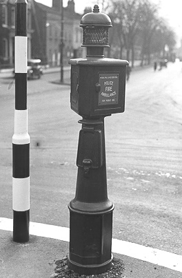
1. "Post, P.A. No. 1"
 A
specially-constructed street pillar, known as “Post, P.A. No. 1” is provided to
accommodate all necessary equipment for a street call-point. A
specially-constructed street pillar, known as “Post, P.A. No. 1” is provided to
accommodate all necessary equipment for a street call-point.
2. Public door
The head of the pillar is of triangular shape. One side carries the protecting grille, the
public call door with its buffer-closing device, and the pin for operating the impulse
mechanism.
3. Maintenance door
On another side is the maintenance door, which is hinged along the bottom and fixed on top
with two captive screws of triangular shape, for which a special tool known as “Key,
Pillar” is required.
4. Power Isolator switch
A flat-headed adjustable screw is provided in this door to press the plunger of the
power switch, which completes the local power circuit for the signal light when the door
is closed and cuts off the power circuit when the door is open.
5. Police door
The third side contains a door which is kept locked and through which access is obtained
by means of “Key, Lock, N,” to the police side of the apparatus.
A Desk No. 18 is also fitted as a wring surface for Police use.
6. First-aid compartment
The body of the pillar contains a compartment for the accommodation of a First-Aid Outfit. The door of this compartment is not locked, and has only to. be pulled open in order to
gain access to the First-Aid Outfit; the Outfit, if required, will be supplied and
maintained by the Police Authorities.
7. Base of pillar
The power supply, and telephone lines, are led-in underground to the base of the pillar. The power fuses are fitted on a board fixed across the base, and the telephone protector
is fitted on a board fixed vertically inside the pillar from base to top. This board
accommodates the power and telephone leads on opposite sides with ample clearance. The
boards are supplied as part of the pillar.
8. Cable entry door security
A maintenance door is provided in the base, and is fixed with four of the special
triangular-headed screws, requiring the use of “Key, Pillar.”
9. Lantern
The lantern on the pillar is a Lantern P.A. No. 1.
If the lantern is not required then the lantern entry hole is covered with a
dummy plate. The lantern dome is made of gun metal and a
Bell No. 60A may be
mounted within the dome. The lantern is secured with captive screws of
triangular shape, which require the use of a "Key, Pillar" when
removal is required.
Specification
Specification - S110
Drawings
Specification - Drawing - 61533
Body - Drawing - 61535
Pillar - Drawing - 61534
Details - Public and Inspection Doors - Drawing
-
61537
Details - Power cover, First Aid cover and Door - Drawing
-
61536
Catch and Hinge - Drawing - 61538
Screws and fittings - Drawing - 61538
Desk No. 18 - Drawing - 61540
Power board - Drawing - 61539
Lock No. 12 with Key N - Drawing - CD112
|