A meeting was held on the 17th April
1957 to consider a proposal for a 2000 line all electronic exchange.
It would be designed to include sufficient code capacity to cater for STD.
Tudor exchange, in Muswell Hill, was suggested as this had a low calling
rate compared to most London exchanges and the new exchange would be a
duplicate, so there was an electromechnical backup if required. Costs
were considered and it was thought that most costs would be covered by an
agreement with Joint Electronic Research Committee (JERC) and that the Post
Offices costs would be around £5000.
It was originally planned to go live in March 1960,
but nobody was really sure of the building requirements. After
investigation it was found that additional space for ventilation equipment
(4 tons), standby power with diesel storage, batteries (22 tons) and
auxiliary equipment would require a building extension to Tudor Exchange.
The Eastern Electric Board also requested the provision of a new electric
sub-station.
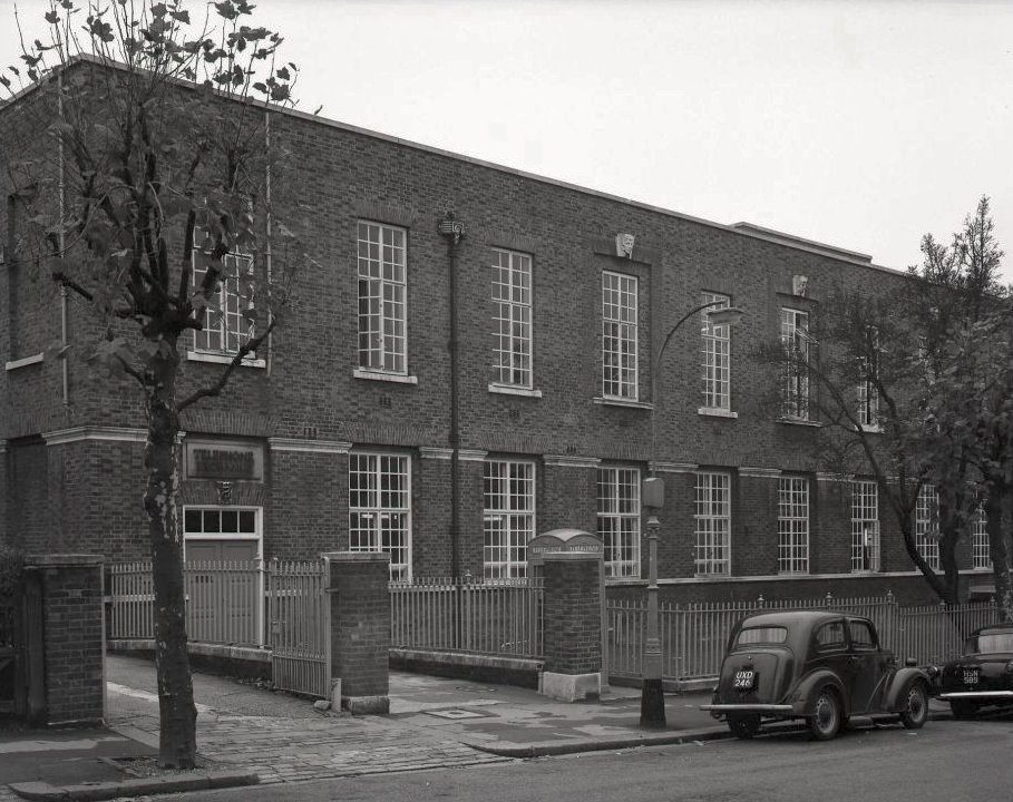
On the 12th December 1962 the first electronic public exchange in the UK went
live at Tudor Exchange at Highgate Wood in London.
Designed by PO engineers at the Dollis Hill research Station, the exchange
was produced by five different companies.
It was experimental and built next to an existing exchange which
would be the backup in the event of a major failure. The exchange used
a mix of transistors and valves, but already better quality transistors were
coming onto the market and there was a new mark two model being designed.
Due to technical problems the exchange was short lived.
An article from GEC
Telecommunications Magazine
An article form Telecommunications Journal Volume 12
An
article from the POEEJ Volume 55, Part 4, Spring 1963
An extract from Post Office Telecommunications Journal Volume 12 No. 2
Electronic Exchange?
By Lionel H. HarrisThe Postmaster
General demonstrated the all-electronic exchange at Dollis Hill last
November. Lionel H. Harris, then Engineer-in-Chief, presiding, discussed the
reasons for this new exchange.
The war accelerated the development of
"Electronics" and the post war period has seen the application of these
techniques in many fields. The ingredients are always much the same;
magnetic storage, pulse techniques, cold cathode tubes, and printed
circuitry, miniaturisation and semiconductor devices.
Automatic
computers, data processing machines and a host of industrial aids have
already emerged from the laboratories. Even before the war it was
foreseen that telephone switching could be done without the use of moving
mechanisms, at a price. Now the technical realization is much nearer
and economic manufacture appears possible.
It may be asked why should we
bother about electronic switching when electromagnetic systems
throughout the world are giving satisfactory service.
I think the
answer is that telecommunications engineers feel that the present
mechanical systems have reached the stages of near perfection within
their own limitations which prohibits any further major advancement and
that although a difficult development and transition period must be
faced, electronic methods are necessary if progress is to be
unfettered and our sights raised to a new level of objectives otherwise
unattainable.
It is probable too that we are influenced by general
trends towards higher frequencies and quicker operation; towards
microseconds rather than milliseconds and the realization that stability
and accuracy are not sacrificed in so doing.
Even so, this higher
level of objectives is not very easily defined-we should certainly save
space by using electronic equipment and, in due course, reduce
maintenance costs but, in the long run, I believe the ultimate advantage
will be in the greater flexibility between the transmission system
connecting our exchanges and the switching equipment; that is, dispersal of
the latter and intermixture with the former. This would be in keeping
with other tendencies which are leading to high frequency cables in the
local networks; for example, for closed circuit television, for data
transmission and, perhaps, even for economy.
It is not an easy task.
The switching equipment is bound to have most of the complexities of
computers and data processing equipment but in addition it must carry
speech and tones, ring bells and operate meters and have other facilities
all without noise and crosstalk. It must also provide a 24-hour-a-day
7-day-a-week service at a price fixed at a low figure by the requirements
of a public telephone service.
The arrangements we have made with
our five switching contractors for joint research and development have
worked well. Apart from avoiding duplication, men of adequate calibre are in
short supply. Moreover the essential requirements of the Post Office for
our large exchanges are a single proven system with all the advantages of
standardization in regard to maintenance, spare parts, engineering,
training, drawings, and so on, which mean so much for plant which must
have a life of upwards of 25 years to be economic.
We are, then,
in an experimental phase but at the same time electronic equipment is
already penetrating into the Post Office telephone service in several
ways. Successful director equipments have long been working at Richmond
and more recently at Lee Green. GRACE, which provides the electronic
control of Subscriber Trunk Dialling at Bristol, has also been
successful, and a notable example of the co-operation which continues to
prove so valuable.
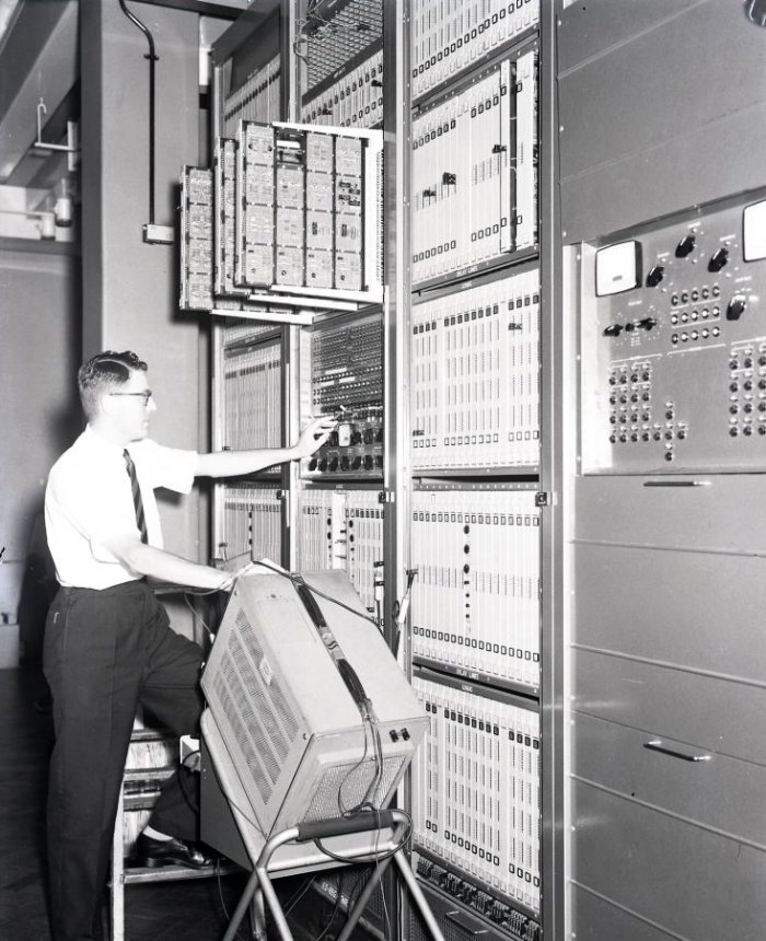
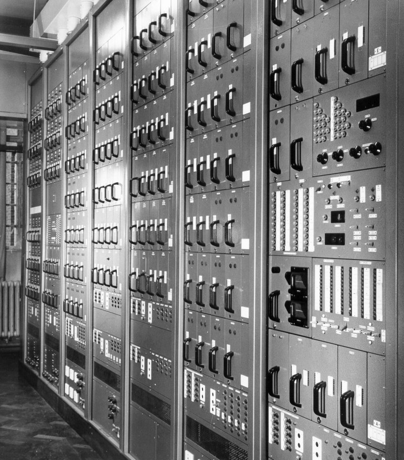
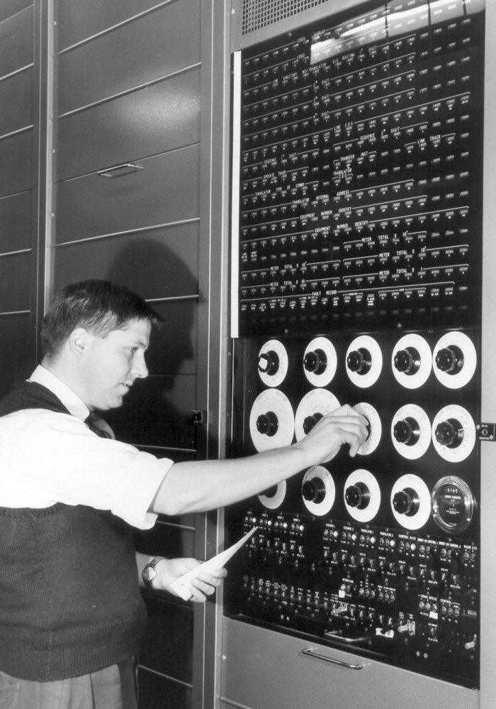
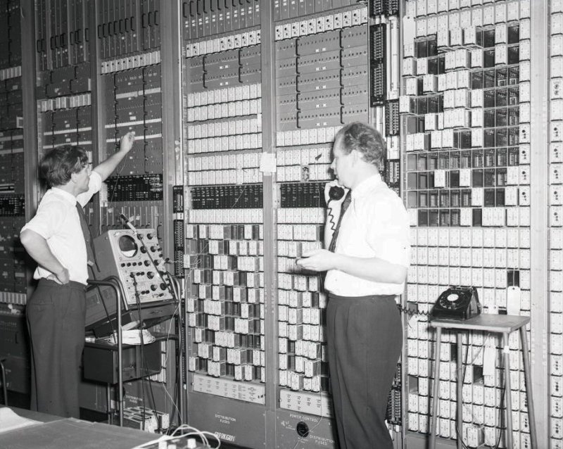
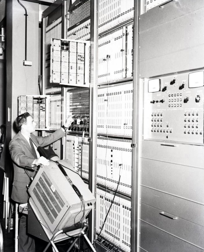
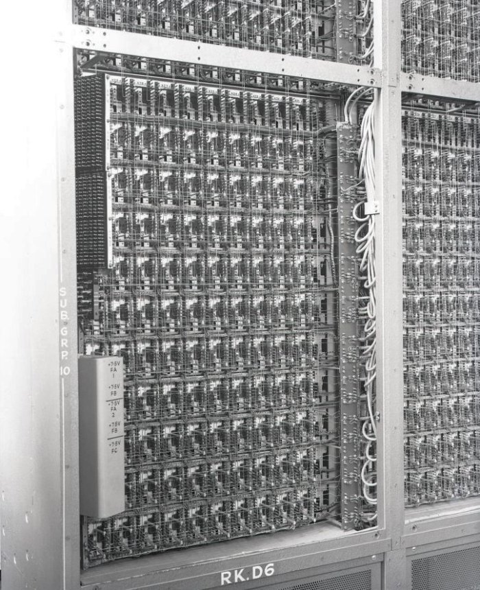
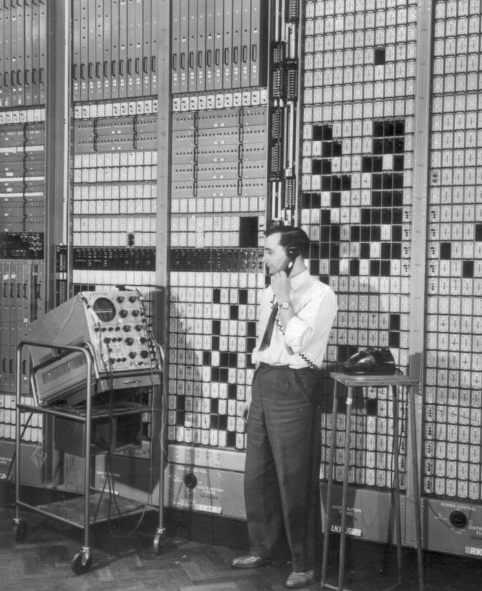
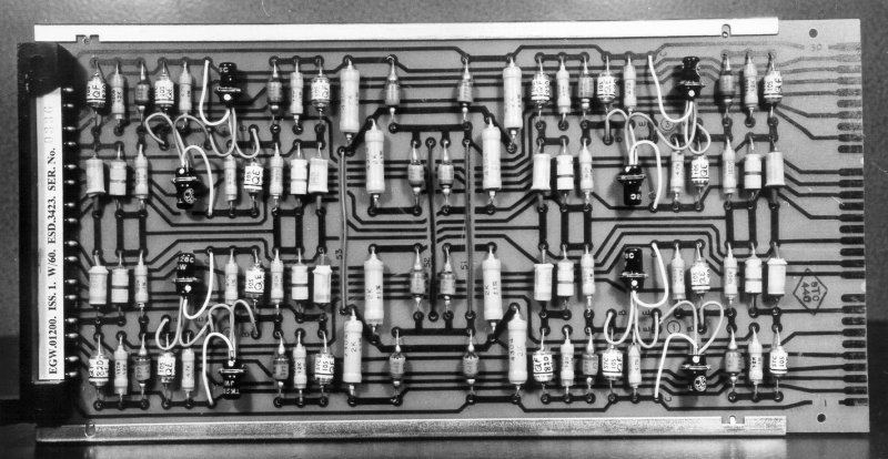
Pictures
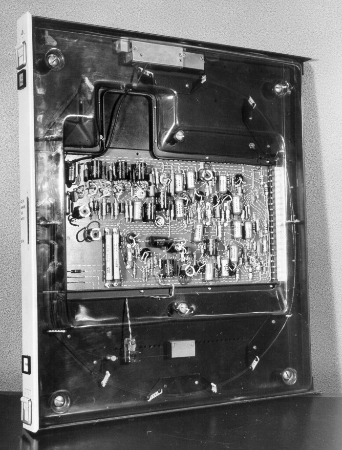
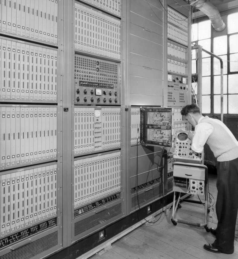
900ms Delay line store (AEI)
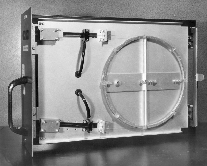
900ms Delay line store (Ericsson)
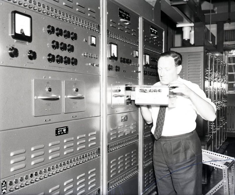
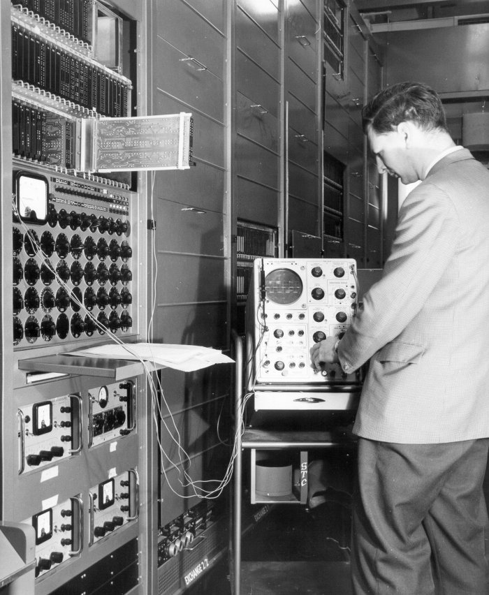
Adjusting an amplifier in the Power Supply Unit
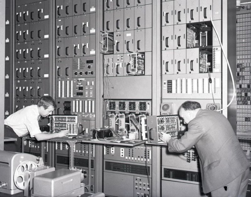
Common register equipment
Common supervisory bays (Ericsson)
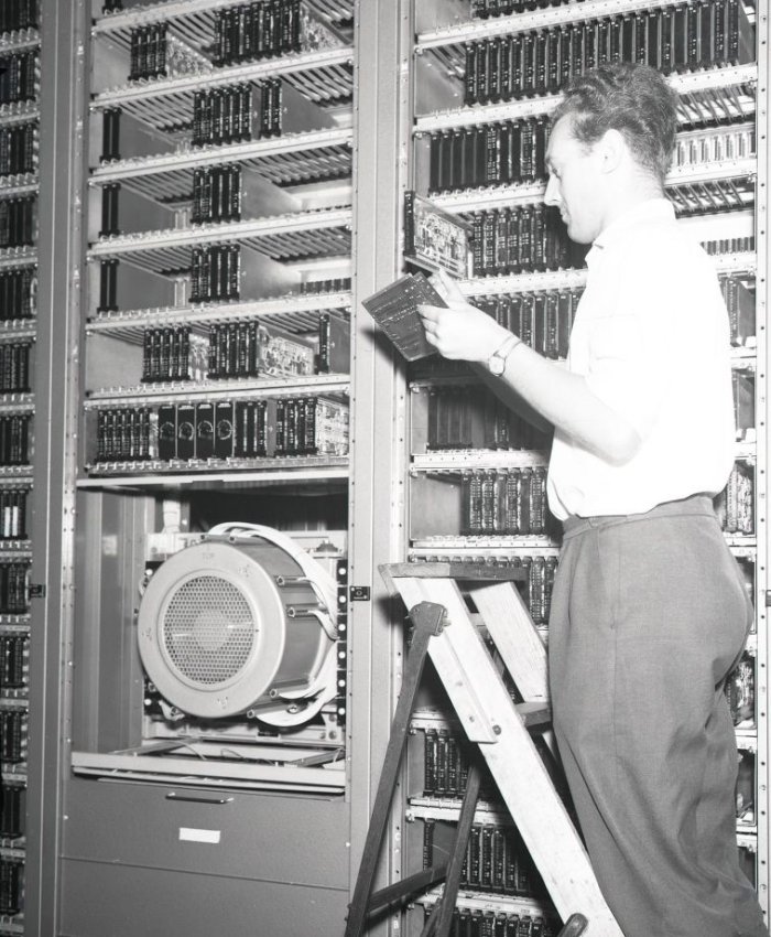
Drum Logic Rack
Magnetic drum control rack (ATE and STC)
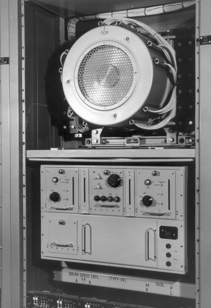
Magnetic drum memory with Synchronised speed control (ATE and Sperry)
Magnetic drum suite (STC)
Register Equipment Assembly (AEI)
Route test equipment (AEI)
Speech Multiplex rack
Speech multiplex rack
S[peech multiplex rack (Rear view)
Subscribers incoming terminations to the right and TDM to the left
Toggle card for memory circuits (ATE) |
 GEC
GEC