|
TELECOM INSTRUCTION
C MARKETING
INSTALLATION
3 Internal
B1010
Issue 3, Dec 1980
TELEPHONE No. 713
PENDANT TELEPHONE
Description, Facilities and Installation
GENERAL
 This Instruction describes the 700 type pendant telephone and outlines its application and installation. This Instruction describes the 700 type pendant telephone and outlines its application and installation.
The pendant telephone consists of a Telephone No. 713 and a Bellset No. 48 or Bellset No. 50B. When
dialing facilities are required a
Mounting, Dial, Automatic, No. 21 should be provided.
DESCRIPTION
The moulded cover is held at the top by two lugs which engage in two slots in the baseplate and at the bottom by a pair of nylon latches which may be adjusted to ensure a secure fixing. The cover is provided with a dummy press button and a label. By removing the dummy press-button and the retaining clip the label may be withdrawn, turned over and replaced so that a white surface shows through the Perspex window. This white surface may be used for displaying the exchange or extension number.
No line cord or terminal block is provided and cable connection to the telephone is made via a hole in the base.
Bellset No. 48
This contains components of the transmission circuit as well as the magneto bell. The moulded cover clips on to the baseplate.
The Bellset No. 48 is to be superseded by the Bellset No. 50B which is based on the 746 family of telephones. The connections and facilities of the two bell sets are similar, but in the Bellset No. 50B the regulator is wired-in and cannot be rendered inoperative.
Mounting, Dial, Automatic No. 21
This consists of a metal mounting frame inside which runs a moulded drawer supporting a dial. The drawer has two protruding nylon crossbars which travel along slides cut out of the sides of the frame. When fully withdrawn the drawer drops into a latched position at a suitable angle for the dial to be used and when lifted restores to its normal position under the action of two constant-torque strip-steel springs, fixed at the back of the frame.
The long securing screw for the dial clamp is accessible from the left hand side of the moulding.

Mounting, Dial ,Automatic No. 21
FACILITIES
The telephone, bell-set and dial mounting provide for most of the standard facilities offered by the Telephone No. 706. It can, however, only be used in CB and automatic Areas. As supplied, the pendant telephone is suitable for exclusive service on DEL's where a press-button is not required. All other facilities are provided by various add-on units.
ADD-ON-UNITS
Press-button and
Switch No. 5A-7
The switch has a single change-over contact unit and the following press-buttons may be fitted:-
Locking: Part No.
1/DBU/345, Grey (ON/OFF) and Part No. 2/DBU/345, Grey (plain).
Non-locking: Part No. 1/DBU/344,
Grey (PRESS) and Part No. 2/DBU/344, Grey (plain).
A press-button can be fitted by first loosening the screws of the press-button guide bracket on the switch. The assembly can then be fitted to the telephone chassis by engaging corresponding notches and tightening one screw.
Auxiliary gravity-switch contacts
The spring-set (Part No. 1/DSP/1279) has a single change-over unit and can be fitted to the bracket
(see picture below).
Mounting bracket
A Bracket, Mounting (Part No.
1/DBR/442) may be fitted to the Bellset No. 48 by one of the printed wiring board fixing screws and a lug which engages in a hole in the printed wiring board. This bracket is used when it is required to fit an additional 2uf capacitor, a Buzzer No. 32C-1 or an additional termination strip. This bracket cannot be fitted to Bellset No. 50B.
Additional 2pf capacitor
A Capacitor, Paper No. 7712-2 and a Clip No. 90 can be fitted on to the mounting bracket (Part No.
1/DBR/442) for Bellset No. 48. The Bellset No. 50B cannot accept an additional capacitor.
Additional terminals
Part No. 2/DST/836 is a strip of 6 connections which can be fitted to the Telephone No. 713 or to the Bellset No. 48. The Bellset No. 50B can accept one or two parts
No. 2/DST/836 without the mounting bracket 1/DBR/442.
Buzzer
The Buzzer No. 32C-1
can be fitted to the Bellset No. 48 with the use of bracket part
1/DBR/442.
The Buzzer No. 32C-3 can also be fitted to Bellset No. 50B without the use of the bracket part
1/DBR/442.
HANDSETS
Handsets Nos. 4, 6 or 14A may also be used with the Telephone No. 713.
 |
 |
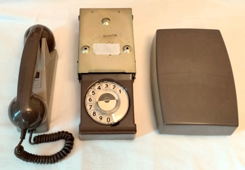
| Internal View showing a
Telephone No. 713 with no additional equipment fitted |
Internal View showing a
Telephone No. 713 with additional equipment fitted:- Switch
5A-7, Part No. 1/DSP/1279 and Part No. 2/DST/836 |
INSTALLATION
The Bellset No. 48 or 50B is supplied with a
"T" bracket.
Fix the "T" bracket in position using at least two of the holes provided.
Hang the upper two holes in the base of the Bellset over the two hooks of the
"T" bracket. With the screw supplied fix the bell-set to the bottom of the bracket through the hole in the base below the printed circuit board.
The Telephone No. 713 is fitted in position by using screws in the slotted holes in the base.
The Mounting, Dial, Automatic No.
21 is fitted in position by pulling out the drawer and using screws in the three holes in the frame. A paper template is provided with each dial mounting. This shows the position of the three holes in relation to the front edge of the desk.
DIAGRAMS
Telephone No. 713 is shown on diagram N813, Bellset No. 48 in diagram N548, and Bell-set No. 50B in Diagram N550. The interconnection of Bellset No's 48 or 50B with the
Telephone No. 713 is shown on diagram N4699.
REPLACEMENT PARTS
The replacement parts which are available, in addition to those parts common to the
Telephone No. 706 and the add-on units are listed below.
| PART |
TO BE REQUISITIONED AS:- |
| Button, dummy, spring for | Part No. 1/DSP/506 |
| Regulator | Regulator No. 1A (Bell-set No. 48 only) |
| Cover, telephone | Part No. 1/DCO/671, Grey |
| Cover, Bell-set No. 48 | Cover No. 78A, Grey |
(Formerly EI, Telephones, Stations, A1067)
Introduced in 1961.Drawing - 92015.
Circuit Diagram -
N813.
Specification - S837.
This telephone superseded the Telephone No. 246.
Made by Plessey, their part number 607/1/00575.
Additional information
| Model | Mark | Grey | Introduced | Remarks | | Tele
No. 713 | Mk 1 | y | 11/61 |
| | | Mk 1 | y | 11/61 | Refurbished |
|