TELEPHONE No. 16 | |||||||
|
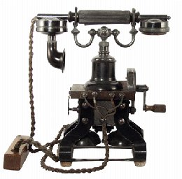
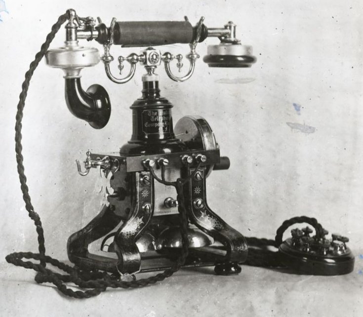
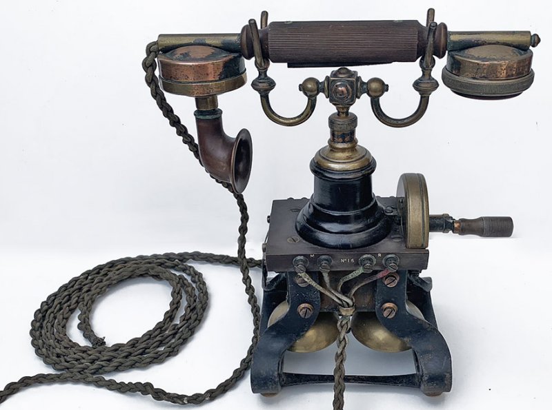
Magneto Table Telephone This is a self contained Magneto table telephone which was nicknamed the 'Skeleton Telephone'. It was the L. M. Ericsson Model No. 375 which was first produced in 1890. The National Telephone Company (NTC) purchased the (No. 375) and Ericsson supplied 100,000 of these telephones to the NTC, in 1889, for use in Britain. When the GPO bought out the NTC, many of these telephones were inherited and the GPO originally called the NTC telephones the "Instrument, Subscribers, Table, N.T. No. 2". The telephones however, were called "Telephone, Table with Generator B" and then later both of them were renamed the Telephone No. 16. This telephone was used on Magneto and CBS exchanges. The transmitter was powered by local batteries housed in a separate battery box. The battery was called a "Battery, Leclanche, Agglomerate, 6 block, 2 cell". If a second receiver was required then a "Hook, Receiver C" and a
"Receiver, Watch D" would be fitted. The handset is a Telephone No. 28. Telephone includes (1910, 1911, 1912, 1913, 1914, 1915 and 1928):-
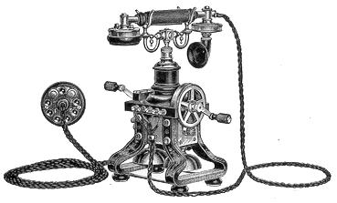
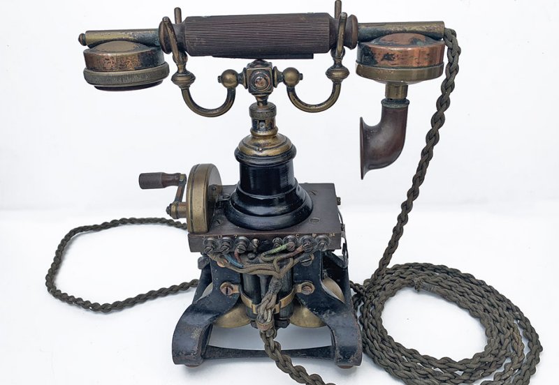
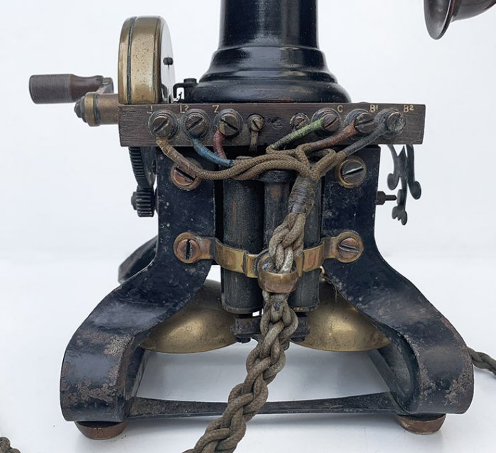
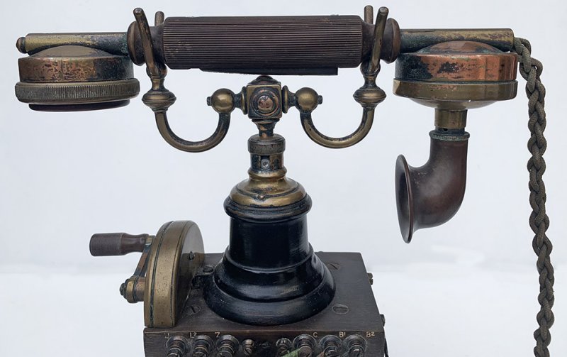
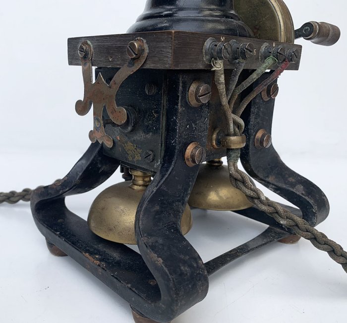
This is an early form of table set and it is perhaps the prettiest magneto telephone which has ever been designed. It is entirely self, contained, except for the local battery, which is accommodated in a battery box. The permanent magnets of the generator form the support upon which the instrument rests, and the magneto bell is fitted between the legs. The induction coil is placed above the magneto generator and the micro-telephone is carried on a cradle which actuates the gravity switch. The instrument is connected to the internal wiring by means of a flexible cord terminating in a Rosette or a connection strip called a Strip, Flexible Cord Connection. Click here for more information. Exchange number label is a Label No. 65.
The dial version of the Telephone No. 16 is extremely rare, concocted under extreme pressure during World War II in the Post Office Factories from the standard Telephone No. 16 by the additional of a dial and the necessary rewiring. An additional contact was added to the ebonite plate and the number 16 engraved on the ebonite had the letter L added so it became 16L. A Plate was added to the base that protruded from the front and held the dial. Telephone No. 16L has a (L)etter dial and Telephone No. 16F has a (F)igures dial. The Telephone No. 18 is the same basic telephone
but with wiring modifications. The Telephone No. 16 has the bell
ringer connected to earth, whilst the Telephone No. 18 has the bell ringer
connected across the line. Telephone No. 16FA
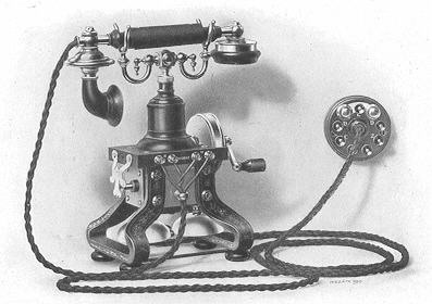
Circuit diagram - N116. Circuit Diagram - TL 208. See also the Telephone Efficiency Committees Report on Local Battery Area telephones. Additional Information An article first published in this form in Telecom Heritage Group Journal, Winter 2014, using material compiled by Jim Foster, Wayne Junop and other un-named authors. The "Ericsson Royal"
Telephone This was the world's first telephone with a one-piece handset, and probably more familiarly known as 'The Skeleton telephone', or, to the British collector as the 'No.16'. Almost all of the early prototypes are now housed in Museums. The handset model was dubbed the 'Ericsson Royal', as it was supplied initially to most of the Crowned Heads of Europe, and the National Telephone Company in England installed one in Windsor Castle at the command of Queen Victoria. The 'Mk.2' model for local installation in Sweden varied according to the system to which they were fitted, some having a lightening arrestor on the plinth instead of in the connection rosette; a smaller bell motor, and in some cases, smaller twin bell-gongs. By 1902, a 5th terminal had been added, and a twin-crank magneto fitted. A button was fitted on some models to open-circuit the ringer coils and short out the secondary winding of the inductor. The 6th edition of the catalogue (1911) was the last to show the swinging arm model. Almost from its first appearance, it was a worldwide success, and was later produced, under licence, in many countries, including the USA, South America, Great Britain and Europe. After 1911, the design remained basically unaltered throughout its long production run, except where minor modifications were made to accommodate local requirements. When the National Telephone Company relinquished its role and assets in 1912, the GPO designated the 'Skeleton' or 'Royal' as their 'Telephone No.16', being extremely conservative, and frowning upon unconventional names for their equipment. Records suggest that production ceased, at least in Europe, in the early 1930's, but many remained in service there until the late 1960's, and in Australia until ten years later. Some in the UK were fitted with dials during WW2, due to shortages of the GPO's 200/300 types. Most were black, but some, made in South America, or reconditioned in Sweden and Denmark to order, were enamelled in bright colours with silver or gold filigree. These are now rare. When the 'Skeleton' telephone first began to attract collectors in the USA in the mid-1950's, a black model in reasonable condition could be bought for $5. By the late 1960's, the price (USA) for a Portuguese manufactured model had risen to $40. Now, one in similar condition stocked by a dealer in the UK could cost between £400 and £800. Restoration of damaged specimens can be undertaken, with diligence, and some spares are still available via Collector's Clubs and Antique Telephone dealers The Ericsson 'Skeleton' or
Open Frame Telephone The prototype was produced in 1882, from what can be seen in the early catalogues and brochures depicting the early Desk sets made by L.M. Ericsson of Sweden. Most of these very early models are now to be found only in Museums, and those in private collections are extremely rare. Basically, the 'tulip' transmitter skeletal model was very handsome. The first two models differed slightly, one having only one receiver, the other, an additional 'bull-ring' receiver connected to two open terminals and suspended on a fixed peg. On a later model, the receiver was suspended on the switch loop peg. These early types were fitted with a rotary switch instead of a sliding crank handle on the magneto. These were made up to and beyond 1911 and some have been discovered that were provided with both versions of the switch. The terminal board on the 'tulip' transmitter skeletal has 2 terminals for the open terminal receiver, and sometimes a second set of terminals for the additional receiver were fitted, the transmitter conductor being fed down through the hollow linkage that was designed to swivel. Some of the variations in these phones could be from different Factories, as Ericsson licensed production in many countries outside Scandinavia. Other firms were also producing copies, unlicensed, some as late as 1930 from the evidence available. The 1892 model was produced in Russia, England, France, the USA, Mexico, Portugal, Denmark and Germany. Most however, were exported from Sweden in the early days. In Australia, many of the Ericsson skeletal phones were installed, and a few were still in use there in the late 1970's. It seems that most 'skeletals'
were manufactured between 1908 to 1914, bearing serial numbers (Sweden) from
726517 to 1202176. Confusingly, some of the earliest Swedish models
and many others produced elsewhere under 'The Ericsson Skeletal
Licence' bore no production numbers at all. One telephone, produced in Sweden
for local use, c.1910, found its way to Australia, and bore the serial
number 802316. The first Skeletal type was designated AC100 and in the catalogue was described as the No.370 magneto table telephone. It was fitted with transmitter RC120 fixed on an adjustable arm (RC521) and a receiver RD110 on a switch hook with cord, RS4300 flex cable and RS9600 terminal block with disc protector. The generators had 2 large magnets, and rang satisfactorily through the ringer (in some cases) and a line resistance of 12000 to 15Kohms. In all models, the magnets formed the legs of the telephone. The resistance of the Bell coils (pair) was usually 300 ohms, but it was produced with coils of between 300 and 1000 ohms to suit the requirements of the system. The second model is the AC110 of 1892, previously the No. 375. It is basically the 5 terminal skeletal with a rotary generator switch on the end of the axle. The crank handle does not slide. This instrument was fitted with a lightning arrestor on the top of the ebonite block, and some had a 'pressel' switch on the handset to reduce background noise when receiving, and at the same time, minimise the drain on the local battery.
The third model is the AC120, previously No. 520, was the most commonly used version in Australia. This has 4 terminals, plus a press-button switch that shorts out the inductor, to give less loop resistance in the receiver circuit for better long distance reception. This switch also cuts out the bells to give more power on the line. This arrangement is useful for testing the subscriber's own phone bell. The fourth model is the AC130/AC140, almost identical to the AC120, but without the push-button. The difference between the two models is that the AC130 has a generator fitted with a "cut-out" with a flat spring, whilst the "cut-out" on the AC140 has a spiral spring. When the generator is operated, the bell on the caller's telephone does not ring. The wiring circuit is also slightly different from that of previous models.
Model number five is known as the No. 385 and is the twin crank skeletal, as it has a handle on each end of the generator shaft. It was made for use where desks were front to front, so that it could be used from either side. The handset and cradle were mounted at 90 degrees to the axis of the generator, to allow space to turn the handles. This telephone is very rare, and as only a few complete specimens have been found, it has been difficult to discover how the second crank was fitted and geared. This model was fitted with 5 terminals. The extra receiver, when fitted to a skeletal, was always wired in series with the main receiver. This is a departure from the usual practice of wiring receivers in parallel. Although most skeletal sets had the crank handle of the generator fixed to its shaft with a screw, some were fitted with a nut & locknut, often leaving exposed thread. It was not an attractive arrangement, but quite functional. Variations in 'tear-drop' shapes between models are probably due to the whim of the foremen in the factory in which they were produced. Not all had 'tear-drops', and the GPO removed tear-drops when they 'recovered' the telephone for refurbishment. Other variations include the distance from the plinth of the instrument to the square 'boss' on the cradle. Most 'skeletals' were black, but some, made to order, have been found enamelled Ivory, Red, Green, and Blue. Cord colours include black, brown, green, and Ivory, to suit the colour of the phone, although most handset cords were brown. The handsets themselves vary, and when damaged, were often replaced by the GPO by one similar in style, but of later manufacture, and not all were fitted with the cup or horn shaped mouthpiece. Over the years, many skeletal phones have been re-built, by private restorers, the GPO, and some quite recently in the Ericsson factories. As a result, minor modifications are often found. Many of the re-built models, especially in Denmark, were then exported worldwide, some for use on the now Automatic exchanges. Where this was the case, various arrangements had to be made to fit the dial onto the framework, but in some cases, in order not to mar the appearance of such a handsome phone, the dial was housed adjacently. In the USA, the dials were housed in the bases of 'candlestick' phones, with the hole for the pillar blanked off with a rubber plug. The skeletal phone is of special interest to many collectors and restorers, and even one in rough shape can, with diligence, be restored over time to pristine condition. Spares are still available, and if an original part cannot be found, some enterprising craftsmen are producing replicas indistinguishable from the authentic. It is interesting to note that in the late 1950's and early 1960's, in North America, these phones could often be found priced at US$5, and a rebuilt set, plus dial, at $50 in black, $60 in colour e.g, beige or blue. ('Deduct $10 if dial not required'). These modified sets, without a dial, were not able to ring dial system subscribers, which accounts for the then (1965) low prices. If collectors had only known then, that such phones would not only hold their price, but, if stored over the years, be worth a small fortune! That of course, is true of many manufactured articles, like old motorcycles etc. A 'Skeleton telephone' in pristine condition in North America would now cost circa $1000, and in the UK, between £500 and £800. The Skeletal set, (known in
the UK as the Telephone No.16), is a beautiful item, and will enhance the display of
any collector.
Instructions for the
Dismantling and Amended article published in 'Telecommunications Heritage Journal', Issue 41, 2002, page 33, and re-issued as Information Sheet No.16 for THG Members. Before commencing work, it would be helpful to refer to N diagram 116 for the schematic circuit, and to a free-hand sketch in THG Journal issue 13, page 27. The Generator Crank Generator Switch Mechanism
Repair Next, check the sliding action of the crank handle barrel over the inner sleeve. Here again, it should be a smooth action, and if there is any sign of interference, remove any irregularities from the outside of the inner sleeve. When all seems well, refit the assembly onto the generator end plate, adjust the switch mechanism as described above, and make a preliminary check on the output of the generator. Under-plinth Rewiring If the telephone has been in a damp place for some time, there will be corrosion, especially where conductors join terminals. Note that the wires attached to the back of the ten larger terminals are secured with grub screws, and these may be too corroded to be unscrewed. Should that be the case, scrape off the corrosion, and solder the wires to the clean terminals. Note that the two wires for the bell terminals are simply pushed through holes and secured under the base of their terminals, which can be unscrewed from the edge of the plinth. The Inductor The coil may be secured by means of two small wood-screws into the sides of the wooden turret. If the two coil windings are continuous, leave the coil in place. In the event of a wire being severed flush with the end cheek of the coil, all is not lost. With a very small jeweller's screwdriver, probe the hole where the wire has broken Degrees it may be possible to see the end of the wire. Scrape it with the blade of a pocket knife. At this juncture, it may be wise to confirm winding continuity by using a needle on the end of your meter probe. If there is no sign of continuity, then regrettably, there is little point in continuing. Induction coils for No.16's are unique to the telephone, and a replacement unlikely to be obtained. If the winding proves
continuous, then proceed as follows:- The Cradle Switch The Bell Motor Proceed as follows:- The modified motor can be mounted on the generator frame using a short piece of aluminium angle, and the original threaded holes under the block, armature upwards and outwards. This means that the original striker arm is not long enough, and must be removed. Early striker arms were threaded (10BA) into the armature, but later issues were riveted, in which case, remove it with a hacksaw, and then drill a 1/16" hole in the armature and tap it 10BA. Obtain a length of 1/16" rod ('piano wire' my local US hobby shop labels it, old (Imperial) stock is slightly oversize, and ideal). New supplies, 2mm, are a bit more difficult to thread. Cut it to the correct length, and thread each end with a 10BA die. The striker ball is not easy to tap, it appears to have a hardened casing, but using a fine carborundum block, a spot can be cleared for a centre-pop in preparation for drilling a 1/16" hole. Assemble and adjust until satisfactory operation is achieved. The modified motor will stand out like a sore thumb, but a suitable cover can be made out of thin aluminium or brass. Cut a slot in the middle of each edge to accommodate the eye bracket for the back-lead, which will keep it in situ without other means.
Acknowledgement is also due to the Editor & publishers of AHTS Newsletter, August 2005, for details of early models.
National Telephone Company
GPO
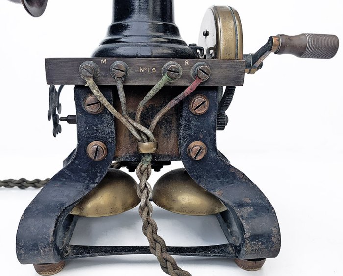
Note the "No. 16" between the centre screws
|
|||||||
Last revised: November 23, 2025FM |