TELEPHONE No. 28 | |||||||||||||||||||||||||||||||||||||||||||||||||||||||||||||||||||||||||||||||||||||||||||||||||||||||||||||||||||||||||||||||
|
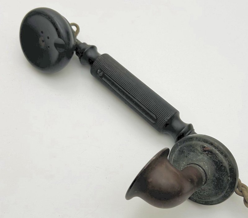
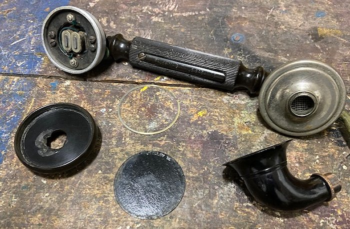
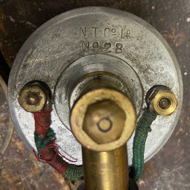
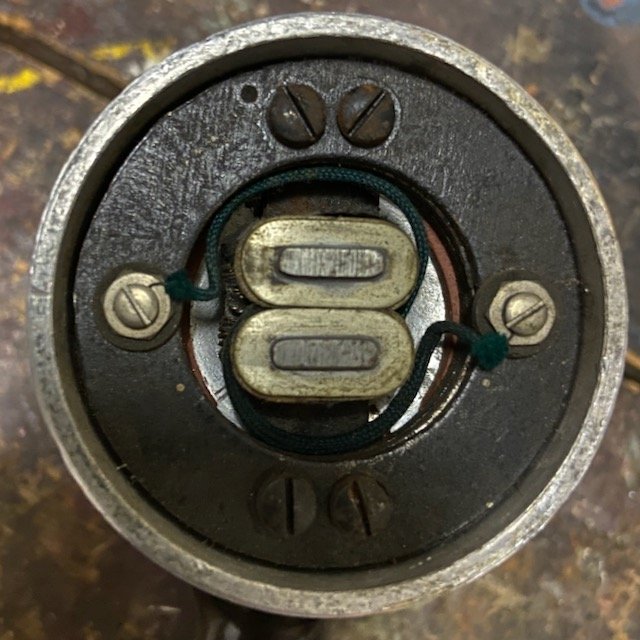
A Local Battery handset with battery cut off switch fitted in the handle. Being local battery it requires a battery power source at the telephone. The handle is made of Ebonite with an integral switch. The switch connects the telephones local battery into circuit, which then powers the transmitter. Originally called the "Telephone, Micro" by the GPO. The NTC "Micro Telephone, Hand, N.T. No. 5" was also renamed as the Telephone No. 28. These types were superseded by the Telephone No. 86 in 1916. This handset was used on many early telephones and could be fitted with a loop or hook suspension eye. In these cases the handset was called the "Telephone, Micro, with loop suspension or the Telephone, Micro" with hook suspension" and a "Contact Hook" or "Suspender for Micro Telephones" would be fitted. Hooks were discontinued in 1915 and only loop types were available. Fitted with a Cord No. 403 (4 way), which was substituted with the Cord No. 421 in 1916. See also:-
Telephone No. 28A was used at Brighton and Glasgow only, and had no switch
In 1916 it included an Earpiece No. 12.
Found in the 1906, 1911, 1912, 1913, 1914, 1915, 1928 and 1946 Rate Books.
Telephone Included (1910, 1911, 1912 and 1914):- No. 28, with loop (1910 and 1911) No. 28, with Hook (1910 and 1911):- No. 28, with Hook and Cord No. 415 (1911):- No. 28A (1912):- Telephone included (1946):- No. 28, with Loop, Telephone Suspension, No. 1 or No. 2 added. (No. 2
added for Mark 237 only) (1928 and 1946). No. 28, with Loop and Cord 4/15A, Brown, 48" (1928 and 1946) No. 28A, without press switch - for Brighton and Glasgow only (1928). No. 28, with press switch (1928)
Note: The Transmitter No. 10 includes a Mouthpiece No. 1 and a Transmitter-Inset No. 3. Circuit diagram - N128. Drawing - 8241 (Mark 4).
Mark 234
Receiver - Rear View
Receiver - Front view
|
|||||||||||||||||||||||||||||||||||||||||||||||||||||||||||||||||||||||||||||||||||||||||||||||||||||||||||||||||||||||||||||||
Last revised: November 18, 2025FM | |||||||||||||||||||||||||||||||||||||||||||||||||||||||||||||||||||||||||||||||||||||||||||||||||||||||||||||||||||||||||||||||