|
Introduced soon after 1936, these relay-switches
are cased in cast iron with two interlocking covers for customer premises
use or steel with a single cover for exchange use. The purpose of this
relay-switch is to isolate low voltage telephony circuits from mains
voltages.
The units consist of a 3000 type relay and up to two
15amp mercury switches (Tubes, Mercury. No. 1). These tubes can be
Make, Break or Change-over actions (the make and break function are
dependant on the angle by which the tubes are fixed).
Where only one mercury tube is fitted, a Tube, Mercury, No. 1, Dummy is
fitted in the spare position. The relay has a standard Change-over contact
(pt) fitted but not wired.
Mercury tubes were used as they did not spark or wear
out. They were also sealed and did not react to the surrounding air.
The relay and any additional components are fitted in the lower
partition. The extra components are generally used
when the relay is operated from a low voltage AC source, such as ringing
current.
Nowadays a flashing lamp can all be done with discrete
electrical components -
click here for more information.
Safety Warning
The glass tubes have the metal Mercury in them. This is a dangerous
liquid chemical and medical attention should be sought if any contact is
made with ANY part of the human body. Never break a tube and always
wear disposable gloves.
Title Description
There are numerous variations of the Relay-Switches and each is described by
the title number.
The title number is interpreted as follows:-
Name - Type - locking (L) or non-locking (NL) - quantity and
rating of mercury tubes
relay cover type
e.g. RELAY-SWITCH No. 3106 N.L. 1-15 AW - this describes a
Relay-Switch, 3106 type, which is non-locking and
includes one Tube, Mercury rated at 15amp and the unit is fitted with an AW cover.
Types Available
| Relay-Switch Title No. |
Relay No. |
Tube Action |
Fitted with |
Use |
| 3101 NL 1-15AX |
3101 |
1M |
|
70v DC |
| 3101 NL 2-15 AX |
3101 |
2M |
|
70v DC |
| 3102 L 1-15 AW |
3102 |
1M |
|
70v DC |
| 3102 NL 1-15 AX |
3102 |
1M |
|
70v DC |
| 3102 NL 2-15 AW |
3102 |
2M |
|
70v DC |
| 3103 NL 2-15AX |
3101 |
2M |
|
70v DC |
| 3104 NL 1-15 AW |
3203 |
1M |
|
70v DC |
| 3106 L 1-15 AW |
4309 |
1M |
|
70v DC |
| 3106 NL 1-15 AW |
4309 |
1M |
|
70v DC |
| 3201 L 1-15 AW |
3102 |
1M |
Rectifier No. 1/12A |
Operated by 50c/s AC ringing |
| 3201 NL 1-15 AW |
3102 |
1M |
Rectifier No. 1/12A |
Operated by 50c/s AC ringing |
| 3301 NL 1-6 AP or AR |
|
1M |
|
Exchange use - 50v DC |
| 3301 NL 2-6 AP or AR |
|
2M |
|
Exchange use - 50v DC |
| 3401 NL 1-15 |
3201 |
1B or 2B |
Rectifier No. 1/12A & Capacitor M.C. No. 102 |
Operated by 50c/s AC ringing |
| 3503 NL 2-15 AX |
3102 |
2M |
Rectifier No. 1/12A & 3 x Resistor, Coils |
DC mains 250v |
| 3601 NL 2-30 BA |
4514 |
1C or 2C |
Uses Tubes, Mercury No. 4 (30 amps) |
Exchange use - 50v DC |
| 4001 NL 1-15 AX |
3102 |
1B or 2B |
|
70v DC |
| 4001 NL 2-15 AX |
3102 |
1B or 2B |
|
70v DC |
Covers
Relay Cover
AW - Used in subscribers premises - cast iron casing.
Relay Cover
AX - Used in exchanges - steel casing.
Operation
The unit is separated into two compartments by a partition across the
middle. This partition has a sliding rod through it, which is operated
by the relay armature. The relay is located in the
lower compartment. The other side of the relay armature operates a
standard contact set. The rod, when the relay is energised, moves
upwards pushing a spring loaded lever, in the upper compartment, upwards.
The end of the lever is located in a swinging arm which holds the mercury
tubes. The swinging arm rotates and the mercury in the tubes cover the
contacts, making an electrical circuit.
In the non-locking version, when the relay is de-energised, the spring in the upper compartment
assists in restoring the swinging arm back to it's home position.
Drawings
Relay Cover AW - 62064
Relay Cover AX - 62065
Relay-Switch 3100 to 3900 AW assembly - 62066
Relay-Switch 3100 to 3900 AX assembly - 62067
Relay-Switch 3100 to 3900 AW arrangements -
TP631
Tubes, Mercury No. 1 - CD240
|
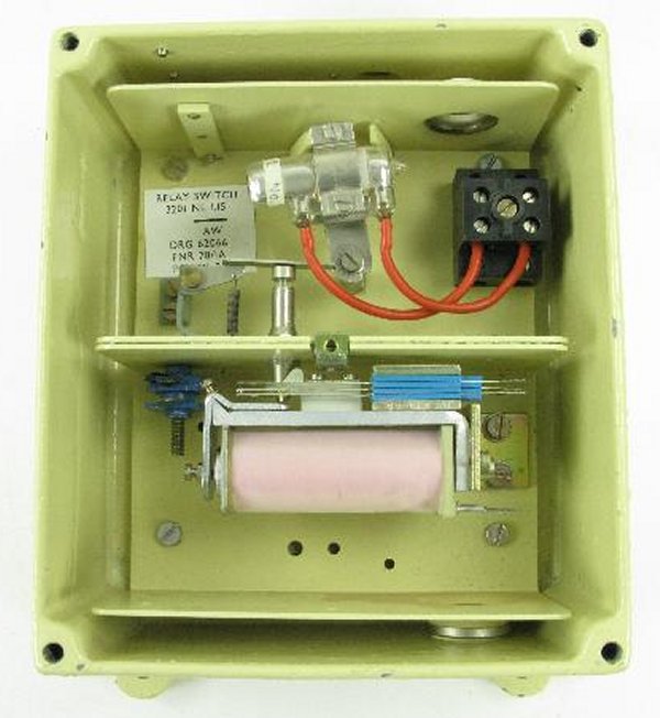
The upper section is where the high voltage mains cables enter the unit
and are terminated. |
 |
The lower section section are where the low voltage telephony cables
enter the unit and are terminated. The relay
and other components are fitted this section. |
| |
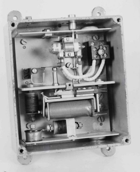
AW type
The picture above is dated 1938. This
is a Siemens made Relay-Switch unit with two mercury tubes.
It had two cast covers, one to cover the mains
section and one to cover the telephony section.
The steel partition in the middle
segregates the two sections.
|
|
| |
|
|
| |
 |
|
| |
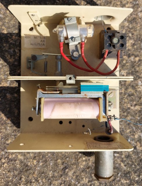
AX type
Used in exchanges with no cast iron
container.
A simple steel cover was fitted.
This one is fitted with a single mercury
tube. |
|
Relay-Switch 3201NL 1-15 AX
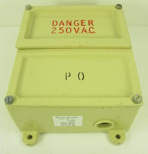
Relay-Switch - AX casing
Can be coloured grey or cream
|