HOW DOES PST WORK! | |||||||
| See also - How to work with telephone wiring Plug and Socket Telephone system (PST) or New Plan was introduced into the UK in the early eighties. This was to allow the easy connection (no engineer needed) to the telephone line of portable customer apparatus. PST afforded a new way of wiring sockets as well, if you could call it new! The wiring was
similar to the way that 200 and 300 type telephones were connected together and effectively
used three wires in parallel.
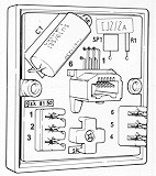
These jacks (shown above) were coloured light grey and had screw terminations. The socket outlet was on the side and not the top. The captive lid variant stopped removal of the telephone plug, which could only be released by removing the lid with the aid of a screwdriver. See picture below.
These above jacks were quickly superseded by Line Jack Unit (LJU) No's 1, 2, 3, 4, 5, 6, 7, 8, 10.
Note that the outlet jack is numbered in reverse compared to the strip connection on the back of the jack.
i.e. outlet 6 is
connected to strip connection 1 (the picture below shows jack/strip
numbering). This information is included for design purposes only and in
all normal cases the strip connection numbers should be used throughout this
document.
Many manufacturers make IDC connectors but BT decided to use those made by Krone. This
effectively standardised this make throughout the Telecommunications industry in the UK. These master sockets stopped being used in customer premises in the late 1980's and were replaced by the NTE 5 socket (see below) which legally allowed the customer to connect wiring to the carriers wiring. Sockets are connected together by means of 6 wire cable. All the secondary sockets are `daisy chained' off the master. Only connect two wires maximum to any IDC connector. A Master socket can be made into a secondary socket by cutting off all the components! Extension bells are wired off connections 3 and 5. SOCKET WIRING BT LINE MASTER SOCKET WIRING SECONDARY SOCKET 1 ----- GREEN/WHITE ---------- 1 ------- A ------------ 2 ------ BLUE/WHITE ---------- 2 ------- 3 ----- ORANGE/WHITE --------- 3 ------- PBX EARTH ------- 4 ----- WHITE/ORANGE --------- 4 ------- B ------------ 5 ------ WHITE/BLUE ---------- 5 ------- 6 ----- WHITE/GREEN ---------- 6 -------
Socket terminal 4 is used generally as an earth connection for telephones connected to old fashioned PBX's. Terminals 1 and 6 were for future use and never really used. In the late 1980's the Network Termination Equipment No. 5 (NTE 5) was introduced. This allowed customers to legally connect their own internal wiring to the Master Socket. The NTE No. 5 was a master socket with a removable plate on the front. The customer wiring connected to this plate and would only be in circuit once the plate was fitted back in place. Effectively, this was a demarcation point. Be warned........ The customer can remove the front plate and connect their internal wiring to the plate. The plate is then refitted. The plate locates in an internal socket which is also used as a test point. If your phone line goes wrong - you remove the front plate and plug a known working telephone instrument in the socket that is now exposed. If the line works, then it is your wiring at fault. You are responsible for this wiring - do not call the Network provider! If your house is fitted with any other type of line jack, or you have to hard wire directly onto the incoming line - then this is illegal as only the carrier can connect any wiring into it! Your carrier will fit an NTE 5 if requested to do so. For more information please contact OFCOM. LIGHTNING CAN DAMAGE YOUR WEALTH Go to the lightning page to find out how!
|
|||||||
Last revised: November 17, 2021FM |


 Some LJU's have screw terminations whilst most have Insulation Displacement Connections
(IDC). IDC allows for quick termination as one does not have to solder or use screw
connections. The wire is forced, by the use of a special tool (Wire Inserter), into the slot of a strip of
metal. The wire must be terminated with the insulation intact and two wires can be terminated in one IDC
connector.
Some LJU's have screw terminations whilst most have Insulation Displacement Connections
(IDC). IDC allows for quick termination as one does not have to solder or use screw
connections. The wire is forced, by the use of a special tool (Wire Inserter), into the slot of a strip of
metal. The wire must be terminated with the insulation intact and two wires can be terminated in one IDC
connector.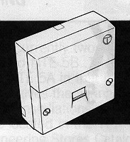 In the UK you can only wire to the Network provider if you have a Network Termination Socket (NTE No. 5 shown to the right). This is the type where you can release the front plate,
to find connectors on the rear. The
network provider owns the NTE and the incoming wiring to the socket.
In the UK you can only wire to the Network provider if you have a Network Termination Socket (NTE No. 5 shown to the right). This is the type where you can release the front plate,
to find connectors on the rear. The
network provider owns the NTE and the incoming wiring to the socket.