GPO Vehicles | ||||||||||||||||
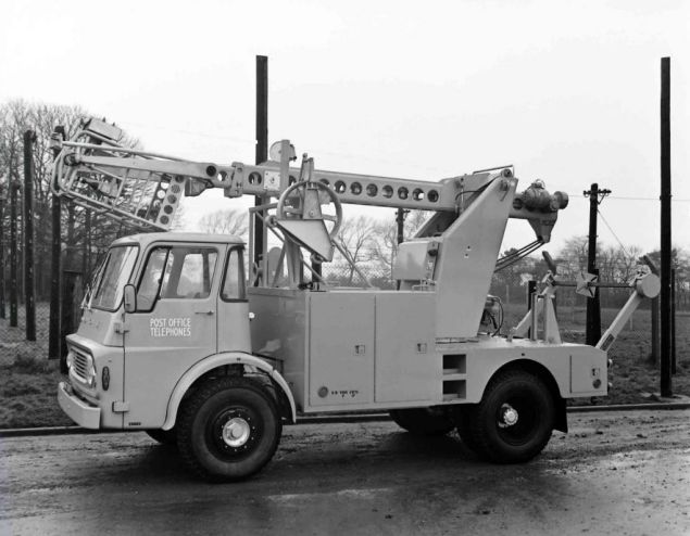
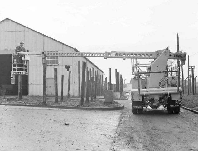
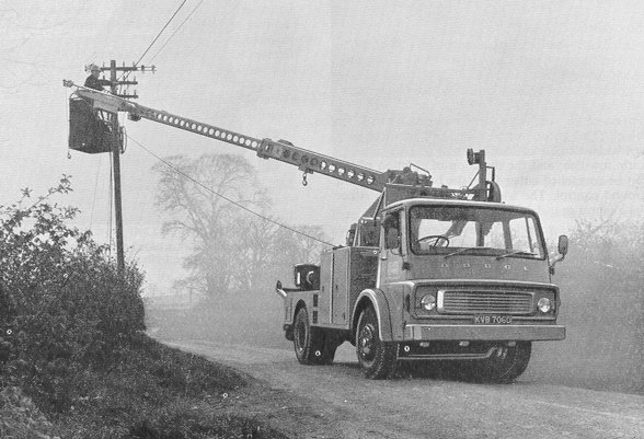
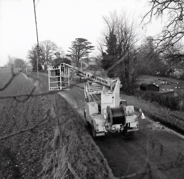
A prototype fitted with King Telstar aerial cabling equipment to allow cabling to continue whilst the vehicle was moving. Pictures are taken at Bletchley Park Training School The top two pictures show short poles which were used for overhead line training
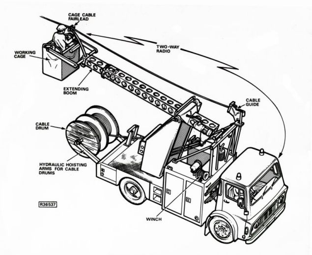
TELSTA SPEEDS AERIAL CABLING Anew machine which, operated by only two men, can erect aerial cables four times as fast as the normal four-to-five-man gang, is undergoing extensive field trials in the Shrewsbury Telephone Area. It is the American-manufactured Telsta T36 - more prosaically called the Aerial Cabling Unit in Britain - and is being used in rural areas to put up the aerial cables which are rapidly replacing the familiar telephone wires. It can erect aerial cables at the rate of between four to six miles a week, the machine paying out the cable in mid-air from the end of its electrically-operated boom as it is driven along at walking pace. The Aerial Cabling Unit consists of a turret-like base and a main boom fitted with an extending inner section. The working platform, in the form of a metal basket, is supported on steel arms at the end of the telescopic boom which has a horizontal reach of 25 ft. 11 ins, and a vertical reach of 36 ft. The complete assembly is mounted on a Dodge vehicle chassis with a two-speed rear axle and a new type of differential lock consisting of two rollers which can be made to bear against the rear wheels to prevent wheel spin in mud or snow. The boom is easily and rapidly raised, lowered or rotated by means of a hand-operated joystick, power being obtained from a propane-driven electric generating set, with an electric self-starter, mounted at the rear of the chassis. The generator drives a number of electric motors which move the boom through a series of chains and chain wheels. If a chain breaks, the working platform can be manually rotated and safely lowered to the ground. The new unit can carry more than 30 cwt. of cable on two arms at the rear of the chassis so that additional cable-carrying transport is unnecessary. The arms can be hydraulically raised and lowered for loading and unloading cable drums. The payload of the basket is five cwt. and in addition nearly a ton of suspension wire can be carried in the well of the vehicle. As the machine moves along its route between poles, the aerial cable can be paid out under tension obtained by electrically-operated drum brakes mounted on the cable drum spindles and controlled by the driver in his cab. The machine stops only briefly at each pole, the operator boring a hole through it with a quick-change combined electrical drill and torque wrench, passing through a bolt and tightening the clamp with the wrench. This operation takes only a few minutes. The machine also has a small but powerful three-speed winch so that at no stage does cable have to be manhandled. This winch - called the electric towline - is used by the Americans to carry out a number of specialised tasks, including passing cable behind poles. Shortly after the machine arrived in Britain from the United States, Mr. J. S. Kennedy, factory manager of the Telsta Corporation, was flown over to supervise the training of Post Office teams in its use and maintenance. First reports indicate that the trials will be successful and that use of the new Aerial Cabling Unit will not only increase productivity but also take much of the hard work out of aerial cabling. An extract from An Aerial-Cabling Unit INTRODUCTION Some three years ago, the pole-erection unit was introduced and is now in wide use throughout the country. Attention is now being given to improving methods and techniques of erecting and recovering aerial cable. A specially designed machine for use on such work has been available in North America for a number of years. It consists of a vehicle-mounted, telescopic aerial-platform, equipped with power tools and pulling winch and is used mainly with lashed aerial-cable systems. The general requirements of an aerial-cabling unit are that it should enable the speedy and safe erection of all forms of aerial cable with the minimum of manpower. It should be particularly efficient for the erection of self-supporting cable which has an integral suspension wire, and its use must lead to significant reductions in the overall cost of overhead construction work. GENERAL DESCRIPTION All motions of the bucket can be controlled, either from the vehicle body, or from the bucket itself. A two-way loud speaker system provides communication between the cab and the bucket. The Boom The boom is elevated by means of an electric motor mounted in the turret, which drives the end of the outer boom by means of a double chain. At maximum elevation a limit switch is operated which stops the motor, and another switch comes into operation if the elevation chain becomes slack. This will occur, for example, when the boom is seated in its carrying rest, or when the bucket rests on the ground. Should the elevation chain fail, a hydraulic safety cylinder located on the turret locks the boom in position. After manual release of the valve on the safety cylinder the boom will descend slowly to the ground. The boom is equipped with a lifting yoke and fixed hook, which is rated to lift a maximum load of 2,000lb at a radius of 6ft. The Turret Should there be an electrical failure of any motor. all motions of the boom can be performed manually, although it is necessary to disengage the friction brake before the boom can be rotated. Control switches for the turret and boom are mounted on the side of the electrical panel. These consist of a set of three toggle switches controlling elevation, extension and rotation, and they may be operated individually or simultaneously. Also mounted on the panel is a meter for recording the running hours of the generator set, a socket for the electric tow-line ground control, and sockets for a 110-volt supply. The Work Bucket and Controls For example, pushing the joy-stick simultaneously down wards, forwards and to the right will lower, extend and rotate the bucket to the right. Movement of the control operates corresponding micro-switches mounted at the base of the control, and these in turn operate 110-volt solenoids in the electrical panel on the turret. A stop-start switch for the electric generating set is also provided on the base of the bucket control switch, as well as a toggle switch for controlling the electric tow-line. The Electric Generating Set A self-starter, which operates from the vehicle battery, is provided for the engine. The Chassis To overcome wheel spin on muddy or snowbound roads, the vehicle is fitted with a Dennis extricator, which consists simply of rollers mounted on each end of a solid shaft. By operating two hand screws these rollers can be made to bear against the vehicle rear tyres, thus effectively locking out the differential and preventing wheel spin. Intercommunication Electric Tow-Line The electric tow-line, and the direction of rotation of the capstan, can be controlled either from the bucket, or from a separate ground control. The winch is self-braking in either direction by a worm-gear drive. Cable Storage The cable-drum spindle is equipped with a magnetic brake, and rheostat control from the cab enables the payout tension in the cable to be accurately controlled during cabling operations. Facilities are also provided for the storage of suspension wire in the well situated behind the driving cab. Payout tension of suspension wire is controlled in a way similar to that of cable. ERECTION OF CABLE WITH THE AERIAL CABLING UNIT Direct Placing of the Cable The vehicle is prepared by threading the cable from the underside of the drum, through the fairleads to the forward mounted bullwheel on the vehicle, and out along the boom to the fairlead on the bucket (see Fig. 3). The towline is fitted with a cam-action grip and is fed along the boom to the bucket. The operator takes with him into the bucket all the tools and pole fittings necessary for the section. He then raises and positions the bucket conveniently close to the pole and terminates the cable suspension wire. On completion, he instructs the driver to proceed along the route. The cable drum brake is adjusted to give sufficient clearance tension in the cable as it is payed out from the bucket fairlead. When travelling between poles, the boom is positioned as far as possible in line with the vehicle to avoid unnecessary strains on the machine and unnecessary extension of the boom. As the intermediate pole is approached, the operator instructs the driver to stop and positions the bucket at working height alongside the pole. The pole is then drilled and the cable supports fitted using an electric impact wrench. The cable can now be transferred to rest loosely over the pole support, the driver instructed to move on, and the bucket again moved into its paying out position. Thus, cable is erected at reasonable clearance until the terminal pole is reached. Final tensioning is carried out in two stages. After attaching the winch tow rope grip to the cable, the winch is operated to take in the cable slack up to a tension of about 600lb, i.e. the maximum pull of the winch. A Piab dynamometer with a Tirfor tensioning device is then attached to the pole and the suspension strand which has been stripped from the cable. The Tirfor is used to apply the final tension and the strand terminated. During tensioning, the driver may need to check that the cable has not fouled branches, and, since up to 20 spans may have been erected, a bicycle together with a radio transmitter, has been found useful. On completion of tensioning the vehicle returns over the route inserting the "anti-galloping" twists, and clamping or binding in the cable at intermediate poles. Variations in the sequence of events may be necessary depending on the route conditions, and some examples are given below. At road crossings it is usual to attach a temporary clamp to the cable close to the pole fitting. This prevents the cable dropping across the road should tension be released inadvertently. If clearance is doubtful, a temporary suspension rope, with cable pulleys attached at intervals along its length, can also be erected to support the cable across the road. Where the route is long enough to require more than one length of cable, a temporary stay is normally necessary at the jointing pole to ensure that successive cable lengths can be fully tensioned as they are erected. Alternatively, the first cable length may be made off temporarily at the jointing pole at "payout" tension. The next length can then be cabled back to the jointing pole, and both cables tensioned simultaneously, without erecting a temporary stay to stabilize the pole. Where an obstruction occurs towards the end of a section, the cable can be temporarily clamped at the last pole before the obstruction, and the remaining cable taken off the drum and left at the pole. With the vehicle at the terminal pole a towline can be taken back over the route on foot to pick up the cable end. The winch can then be used to haul in the towline and the cable. Drawing-in the Cable The cable drum is parked on a trailer at a convenient position near the first pole with the drum-spindle braked to prevent over run and give some tension to the cable. The cable end is taken up the first pole and passed through a pulley block fitted to the pole. The towline passing through the bucket fairlead is then attached about 4 to 5 yards from the cable end, and the cable is drawn in as the vehicle moves along the road. Where the cable has to pass behind the pole, or through the arms, the vehicle is stopped and the cable is temporarily anchored using a separate line and grip. The towline may then be removed from the cable, passed round the pole, or through the arms and re-attached to the cable. After removing the temporary anchor, cabling can proceed as before. After terminating at the final pole, the unit returns to the first pole to pull up, tension, and make-off. Since braking at the trailer is lin1ited, payout tensions are necessarily lower in this 1nethod and sag is greater. It is essential, therefore, to use the ten1porary suspension line and cable rollers where clearance is important. Temporary suspensions are recovered during the final run over the route to insert twists and bind in the cable. Lashed Cable Systems CONCLUSIONS The joystick control is simple and positive, and with very little experience the operator is able to place himself quickly and accurately in any desired working position. Training of crews for this machine has presented no problems, and there is no undue difficulty in using the unit safely and efficiently after a few hours instruction. The trial has shown quite clearly that aerial-cabling work can be performed easily and safely by two men using the unit, with a saving of better than half the man hours. More important, perhaps, the crew experience far less fatigue than with normal manual methods of construction. It is clear that the improvement in productivity is high, particularly on those routes carrying heavier cables of the trunk or junction type, or the longer local cables. The majority of cables erected today are, however, of the smaller local type, and the scope for this high-cost in1ported machine is limited. The experience gained has been invaluable, and work is already proceeding on the development of a cheaper, British-made machine. Although this will have rather fewer facilities, it is hoped to produce a unit which will handle the more common, sn1aller cables, and will have a wider application in the field of overhead wiring and cabling construction. ACKNOWLEDGMENTS
|
||||||||||||||||
Last revised: February 01, 2024FM3 |