TELEPHONE No. 712 | |||||||||||||||||||||||||||
| Click
here for history of the development of the Trimphone 700 Type telephone circuit description 700 Regulator operation Sales Circular 342/65 - Telephone No. 712 Sales Circular 121/68 - Telephone No. 722 Extract from Hansard General fault finding on your phone Deltaphone Trimphone Prototype Other colours - Public survey POEEJ Article on the Telephone No. 712 trial Circuit diagram - N812. Specification - Mark I is S(W) 2072 and Mark II is S(W) 2091. Designed and manufactured by STC, their Deltaphone. Introduced in 1966, these telephones were on field trial and available mainly in the London Telephone Region North West Area. By 1968, a modified heavily modified version of this telephone was available and called the Telephone No. 722. Once the original stock were exhausted the new variant would be installed.
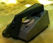
The Trimphone started life in 1964 as the Telephone No. 712
Trimphone. The (then) modern design incorporated the novel feature of dial
illumination, tone calling and a unique handset. The initial four letters
of the name Trimphone stand for Tone Ringer Illuminated Model. The
Trimphone was designed by Martyn Rowlands and produced by STC, who marketed the
phone as their Deltaphone.
The Trimphone was the first in the BPO range to use a tone caller which
warbled at around 2000Hz modulated by ringing current. The volume of the
ringer gradually built up over the first few cycles of ringing current.
There is a volume control in the base of the telephone with LOUD, MEDIUM and
SOFT settings (OFF setting was achieved by slackening off a screw on the
tone ringer board inside the phone - engineers work). Some people were able
to mimic the sound of the tone ringer by simultaneously whistling and
wobbling their lips... a vulgar habit which should be frowned upon. In a reply to a Parliamentary question about Trimphone numbers, the Postmaster General replied that around 36,000 had been installed by June 1968 and that monthly sales had averaged out at 4,350. By 1980 there were 1.6 million in operation out of a total telephone population at that time of 27 million. There was also some concern about the luminescent dial which glowed green in the dark. This effect came from a small glass tube of tritium gas, which gave off beta radiation and made the dial fluoresce. Although the radioactivity was equivalent only to that given off by a wristwatch it was felt wise to withdraw this facility as public concern over radioactivity grew. Another problem with the dial version of the Trimphone was its
light weight, 0.8kg compared with 1.4kg for the 700-type telephone and 2.6kg for the
300-type telephone. This led to the complaint that on slippery surfaces the
telephone turned and slid whilst dialling. The fix for this was to wet the
feet and the phone stuck to the table! Notable differences between the Telephone No. 712 and the Telephone No. 722
Telephone No. 712 has:-
An article by Alan Hollingdale I was working as a draughtsman at STC in 1965 and arrived there just at the right time to be given an excellent project to work on. I was handed a futuristic looking phone which was, due to it's shape, known as the Deltaphone. The concept of the design had come from Lord Snowdon's office and all the drawings were marked PROTOTYPE and were unfit for major production work. One of the first things that I had to do was to design a new cover fixing that could be removed by a single screw either on the rear or on the top. The "rather strange" reasoning for this was that to remove the three screws from the underside, although it was envisaged that an engineer would hold the instrument in his hand to do so, it may scratch the customer's highly polished table if placed upside down to remove the screws. Initially, a single captive metal screw was positioned low down at the centre of the rear but this proved to be rather fiddly in trials and so a single nylon screw was put in the centre of the top under the handset. This then presented the problem of how to secure the front of the cover to the base. Several ideas were worked up into trial models, a major criterion being that of ease of tooling/moulding. Eventually a compromise was reached and is visible, or rather invisible, on all subsequent models. On the later production model you will also notice that the ribs on the underside of the base were deemed an unnecessary cost and so it is now smooth. During the year or so that I was working on the Deltaphone several irksome modifications were made in order to reduce production cost. I can recall on one occasion when I had just completed the layout of the tone board for the second or third time when I was presented with a different capacitor. This particular 'cheap' component's terminals were a few thou further apart which meant redesigning the whole blasted thing again - all to save something like a halfpenny per thousand! Along with all the other design changes it was decided to have two separate printed circuit boards keeping the tone generator separate from the main phone unit. Another cost saving exercise was to do with the etching of the printed circuit boards. Cost was not a consideration on pre-production units but when it came to the amount of copper to be etched away from the PCB's it had to be kept to a minimum. The removal of too much copper would not only be wasteful but also affected the etching medium which would quickly become contaminated. In 1966 I was also working on the push button variant although it was to be several years before it was offered to the public. Well, that's about as much as my ageing grey matter can recall after so long!
Field Trial of the Trimphone Telephone No. 712 A new type of telephone incorporating several novel features and having a very modern appearance is undergoing field trial. The instrument has a handset of unique design and utilises a tone caller instead of a magneto bell. INTRODUCTION The Handset The receiver is retained in position by a metal plate and a rubber ring seal between the receiver and the earpiece. Two lugs, which are an extension of the metal plate, clip the earpiece on to the handle by engaging behind two moulded bosses; a special tool, which can be inserted in the joint-line, is required to release these clips. A light-weight helical cord, with four conductors and a p.v.c. covering, connects the handset to the body of the telephone. The Telephone
Body The dial is mounted on the base plate and protrudes through a close-fitting hole in the cover; to permit alignment it is flexibly mounted by a three legged P.V.C. moulding. The pulse mechanism is identical to that of the Dial No. 21, but the body is modified to contain a luminescent tube behind a translucent number ring. A thin coating of aluminium is vacuum deposited on the surface of the cavity within which the tube is fitted; the coating provides a highly efficient reflector to make the best use of the light emitted by the tube. This is a sealed glass tube that has a fluorescent coating on the inner surface and is filled with a small quantity of tritium, a low-intensity radioactive gas (an isotope of hydrogen). The low-energy Beta radiation energises the fluorescent coating and is then absorbed by the glass. The secondary radiation (Bremsstrahlung) which then arises has been confirmed by both the Post Office Radiological Officer and the Radiological Protection Service to be much less than the recommended maximum for luminous wrist watches. The tube is expected to have a useful life of at least 10 years. The illumination, although unnoticeable under normal levels of incident light, is ample to enable the telephone to be located and used in the dark. The fingerplate, transparent to avoid masking the low-level illumination as well as being an attractive design feature, is moulded in smoke tinted polycarbonate., a tough thermoplastic. For those installations requiring a single press-button, a micro-switch with a change-over contact can be mounted at the front of the base plate with its polycarbonate. press bar projecting beneath the front edge of the cover. The 4-way line cord enters the base plate at the rear edge, whereas the handset cord enters at the side, conventionally from the left, but it may be transferred to the right if preferred. The Tone Caller Circuit Arrangement PERFORMANCE FIELD TRIAL ACKNOWLEDGEMENT An unusual Telephone No. 712 in clear plastic - used for promotional purposes
POST OFFICE ENGINEERING DEPARTMENT
l. SCOPE OF INFORMATION 2. GENERAL 3. DESIGN 4. HANDSET The receiver is held in position by means of a spring clip which is screwed to the earpiece moulding by four screws. The terminals of the receiver extend beyond the clip plate and a polythene membrane is clamped beneath the clip to insulate the terminals from the transmitter, should they touch. The transmitter is fitted adjacent to the receiver under the earpiece and the mouthpiece is coupled to the transmitter by means of an acoustic horn. The transmitter is fitted between the lugs of the horn adaptor, the frame terminal being positioned in the corner of the opening to avoid its fouling either the earpiece or the clip.The earpiece is located by a tongue which slides inside the body moulding and a close fit is maintained by two spring clips which engage on lugs suitably positioned on the body moulding.An extra light coiled handset cord has been chosen to prevent drag on the handset or the telephone set.The mouthpiece is in the form of a grid which covers the opening to the acoustic horn.5. THE TELEPHONE SET The gravity switch assembly is screwed to the inside of the cover and the springset is operated by a lever mechanism which pivots on a knife-edge. The lever is acted on by the plastic cradle bar which is hinged to the ends of the lever.The dial is supported above the tone caller by a three-legged pliable moulding which provides a tight fit on three pillars projecting vertically from the base through spring collets in the printed wiring board of the tone caller.The tone caller is also located by a fixing screw. The cover which is shaped at the top to accommodate the handset is held firmly to the base by three fixing screws.6. TONE CALLER The volume settings are obtained by turning the knurled edge of the volume control knob found slightly projecting from one side of the base near the front.When the telephone is to be used as the extension instrument in a Plan 1A where the "off" condition is required this can be achieved by:-
7. DIAL 8. CORDS The conductors are terminated on a centrally placed terminal strip. The cord enters via keyed hole and can be locked by twisting the cord so that the splines in the brass ring are about 45 degrees out of line with the keyway. The handset cord enters the middle left hand side of the base and terminates on the same terminal strip. This cord also enters the handset by a keyed entry hole and the conductors travel the length of the handset body to the connections on transmitter and the receiver.
PART II l. STOCK OF SPARE PARTS FOR REPLACEMENT PURPOSES A normal stock of spare items for replacement purposes consisting of the apparatus listed below should be held at the faultsmen's headquarters. 2. FAULT PROCEDURE~Attention is drawn to TELEPHONES, General D6028 which describes the action to be taken by a maintenance man when he has dealt with a fault on Newly Developed Apparatus covered by the Fault Reporting Card Scheme. Telephone No. 712Regulator No. 1A Receiver Inset No. 3T Transmitter Inset No. 15 Cord, Instrument No. 4/101AX Grey 7.5" Cord, Instrument No. 4/102AX Grey 60"
DISMANTLING AND ADJUSTMENT OF COMPONENTS 3. EARPIECERemoval. Open gap of the 45 degree join line between the earpiece and the body, slide the blades of the 'Key, Earpiece' in the join line until the cut-outs on the blades locate on the lugs of the clip. Pinch the ends of the key together to press the clip lugs and release the earpiece which will hinge away from the body. Replacement. Slide the tongue of the earpiece between the transmitter and the body moulding taking care not to trap the leads. Grip body across its width to counteract the outwards pressure of the clip and hinge the two together. Both parts should be pressed together until two sharp clicks are heard indicating that the clip is properly located.See Handset No. 8 4. MOUTHPIECEThis should not be removed. 5. TRANSMITTER INSET N o. 15Removal Withdraw the earpiece and disconnect leads of transmitter. Insert a Screwdriver No. l between the faces of the transmitter and horn and turn slightly to lift the transmitter clear of the retaining lugs on the adaptor, carefully ease the lugs outwards if necessary. Replacement 6.
RECEIVER 3T Replacement 7. COVER Place cover on its top face so that the gravity switch is operated. Replacement 8. DIAL Replacement 9. HANDSET CORDRemoval Handset Termination. Withdraw earpiece. Pull back membrane from over the nuts on the receiver. Disconnect leads from transmitter and receiver and cut off cord terminations. Grip cord grommet, turn approximately 90 degrees in an anticlockwise direction and pull the cord clear of the handset. Base Termination. Remove cover. Withdraw the fixing screws of the termination strip and lift clear as far as the flexible leads will allow. Lift handset cord away from side of base and disconnect.Replacement Before allowing the raised splines of the brass ferrule to enter the keyway align the cord grommet with its mating recess. Turn the grommet in an anticlockwise direction until the splines line up with the keyway. Push the grommet tight against the mating face and turn clockwise to secure. Connect the blue wire to the frame terminal and the white lead to the centre terminal of the transmitter. It should be ensured that the frame terminal is positioned in the corner. The green and red leads being connected to each terminal of the receiver.Pull the membrane over the terminal nuts and finally replace earpiece. Base Termination. Connect the leads to the termination strip, place the grommet in appropriate slot in the side of the base and secure termination strip in position.10. LINE CORD Replacement 11. REGULATOR NO. 1A 12. GRAVITY SWITCH SPRING SET (a) Contact Cleaning. Use a Cleaner, Contact No. l, check adjustments and if necessary, readjust as described in (b). (b) Spring Set Adjustment (1) Release the coiled spring from the spring set bracket located above the lifter comb. Remove the three dome headed screws and lift the spring set clear of the cover. Care should be taken not to disturb the ribbon cable more than is necessary to provide access to adjust the spring set. (2) Straighten springs with Pliers Adjusting No. l and adjust to lie parallel with the mounting. Tension the tongues of Spring No. 3 against the buffer to obtain a pressure of 12-16 gms. measured with a Gauge, Tension No. l just in front of the contacts. (3) Tension Spring No. 2 against Spring No. l to give a contact pressure of 12-16 gms. (4) Tension Spring No. 5 against Spring No. 4 to give a contact pressure of 12-16 gms. (5) Operate the lifter comb by hand so that Spring No. 3 is clear of the buffer and check that the contact clearance between Spring No. l and No. 2 is greater than 15 mils and between Springs No. 4 and 5 a contact clearance greater than 20 mils. (6) Operate the lifter comb by hand and check that Springs No. 4 and 5 break before Springs No. l and 2 (i.e. With a perceptible gap between Springs No. 4 and 5 while Springs No. l and 2 are still made).( 7) When releasing pressure on the lifter comb, Springs No. l and 2 shall make before Springs No. 4 and 5 (i.e. Springs No. l and 2 are made while there is a perceptible gap between Springs No. 4 and 5) .( 8) Replace the spring set in the cover, secure bracket with fixing screws and replace coiled spring.( 9) With the gravity switch depressed by hand check that Spring No. 3 is lifted clear of the buffer.13. TOOLSThe following tools are required for maintenance of the telephone:-
POST OFFICE ENGINEERING DEPARTMENT
1. SCOPE OF INFORMATION 2. GENERAL 3. DESIGN 4. HANDSET (HANDSET No. 8A) The transmitter inset is fitted adjacent to the receiver under the earpiece and the mouthpiece is coupled to the transmitter by means of an acoustic horn. The transmitter is fitted between the lugs of the horn adaptor, the frame terminal being positioned in the corner of the opening to avoid its fouling either the earpiece or the clip. The ear-piece is located by a tongue which slides inside the body moulding and held in place by a non-captive nylon screw. An extra light coiled handset cord (Cord, Instrument No. 4/101AX Colour 7.5") has been chosen to prevent drag on the handset or the telephone. The mouthpiece is in the form of a grid which covers the opening to the acoustic horn. 5. THE TELEPHONE SET The gravity switch assembly is screwed to the inside of the cover and the springset is operated by a lever mechanism which pivots on a knife-edge. The lever is acted on by the plastic cradle bar which is hinged to the ends of the lever. The dial is supported above the tone caller by a three-legged pliable moulding which provides a tight fit on three pillars projecting vertically from the base through spring collets in the printed wiring board of the tone caller. The tone caller is also located by a fixing screw. The cover which is shaped at the top to accommodate the handset is held firmly to the base by three fixing screws. 6. TONE CALL (TONE RINGER No. 2A) The OFF position is not normally available to subscribers
with only one telephone. However when the telephone is to be
used as an extension instrument, e.g. in a Plan 1A, where the "Bell off"
condition is required this can be achieved by:- 7. DIAL (DIAL AUTO No. 30LA) Reference should be made to Engineering Instructions, TELEPHONES, Stations, A 3215 which details the precautions to be observed when handling and storing these items. 8. CORDS The handset cord - CORD, INST, No. 4/101 AX COLOUR - enters the middle left-hand aide of the base and terminates on the same terminal strip. This cord also enters the handset by a keyed entry hole and the conductors travel the length of the handset body to the connections on the transmitter and receiver insets. The following cords are being made available for use with
the telephone:- 9. ADD-ON UNIT The unit is coded Switch No. 13A-1 and is complete with a micro switch with one changeover springset and a button. 10. INSTALLATION The limits on the number of bells that may be joined in series as laid down in E.I. TELEPHONES, Stations D1001 will still apply to tone callers and to a mixture of tone callers and. bells. However since when using one or more tone callers a Thermistor is always required difficulty may arise on long lines where more than four calling devices are fitted and the number of bells exceed the number of tone callers. In these cases a local ringing converter may have to be fitted. The telephone cannot be fitted with add-on gravity switch springsets but can be used as an extension on a 14-wire PBX if a 2 wire/4 wire conversion unit is available. 11. INSTRUCTION CARD 12. AVAILABILITY Dated 1966 Additional information
|
|||||||||||||||||||||||||||
Last revised: June 29, 2026FM |


 The
cover of the telephone body, moulded in ABS, is attached to the
toughened-polystyrene base-plate moulding by three screws, which are
inserted from the under-side. The gravity-switch bar, moulded from
smoke-tinted polycarbonate. to match the dial finger-plate, passes freely
through two holes in the cover and is attached by a pivot rod to a bell
crank. The gravity-switch spring-set is mounted on a metal bracket attached
to the cover; this bracket is extended to form two knife-edge bearings for
the bell crank, and a helical spring between the two parts keeps them in
close contact and provides the restoring force for the gravity-switch bar.
The
cover of the telephone body, moulded in ABS, is attached to the
toughened-polystyrene base-plate moulding by three screws, which are
inserted from the under-side. The gravity-switch bar, moulded from
smoke-tinted polycarbonate. to match the dial finger-plate, passes freely
through two holes in the cover and is attached by a pivot rod to a bell
crank. The gravity-switch spring-set is mounted on a metal bracket attached
to the cover; this bracket is extended to form two knife-edge bearings for
the bell crank, and a helical spring between the two parts keeps them in
close contact and provides the restoring force for the gravity-switch bar.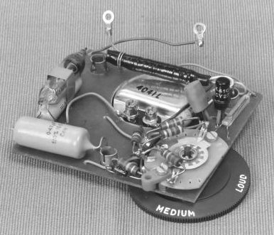 Beneath
the dial is mounted the printed-wiring board of the tone caller, which is
used instead of the more usual magneto bell; it emits a pleasantly-modulated
tone, the volume of which is adjustable. The tone-caller circuit consists of
a single-stage transistor oscillator tuned to about 2,000 c/s, the basic
waveform being modulated by the ringing frequency. The output feeds a
modified rocking-armature receiver that is positioned by the circuit board
above an orifice in the base. The diode Dl acts as a half-wave rectifier of
the incoming ringing current, resistor R1 and capacitor C1 smooth the
waveform, resistor R3, with other resistors in the circuit, controls the
bias applied to the transistor, and the frequency of oscillation of the
circuit is determined by capacitor C3 and the inductance of the receiver. Thermistor TH1, diode D2 and capacitor C2 provide a threshold to guard the
circuit against false operation by random pulses on the line. Thermistor TH2
in parallel with resistor R4 delays the build up of the volume if the LOUD
or MEDIUM settings of the volume control are used, and resistors R5 and R6
attenuate the output for MEDIUM and SOFT settings of the volume control. The
knurled edge of the control knob projects through a slot in the rim of the baseplate so that it is just visible beneath the edge of the cover. Instead
of a bell on/off switch, a locking screw can be withdrawn from the volume
control, permitting the knob to be turned to an OFF position. The shunt
resistor R2 is incorporated to improve the performance of an additional
magneto bell, which may be connected in series with the tone caller if
required.
Beneath
the dial is mounted the printed-wiring board of the tone caller, which is
used instead of the more usual magneto bell; it emits a pleasantly-modulated
tone, the volume of which is adjustable. The tone-caller circuit consists of
a single-stage transistor oscillator tuned to about 2,000 c/s, the basic
waveform being modulated by the ringing frequency. The output feeds a
modified rocking-armature receiver that is positioned by the circuit board
above an orifice in the base. The diode Dl acts as a half-wave rectifier of
the incoming ringing current, resistor R1 and capacitor C1 smooth the
waveform, resistor R3, with other resistors in the circuit, controls the
bias applied to the transistor, and the frequency of oscillation of the
circuit is determined by capacitor C3 and the inductance of the receiver. Thermistor TH1, diode D2 and capacitor C2 provide a threshold to guard the
circuit against false operation by random pulses on the line. Thermistor TH2
in parallel with resistor R4 delays the build up of the volume if the LOUD
or MEDIUM settings of the volume control are used, and resistors R5 and R6
attenuate the output for MEDIUM and SOFT settings of the volume control. The
knurled edge of the control knob projects through a slot in the rim of the baseplate so that it is just visible beneath the edge of the cover. Instead
of a bell on/off switch, a locking screw can be withdrawn from the volume
control, permitting the knob to be turned to an OFF position. The shunt
resistor R2 is incorporated to improve the performance of an additional
magneto bell, which may be connected in series with the tone caller if
required. 