TELECOMMUNICATIONS
INSTRUCTION
C MARKETING - INSTALLATION
3 Internal
E 4070
Dec 1970, Issue 1Switchboard
N 1070
General
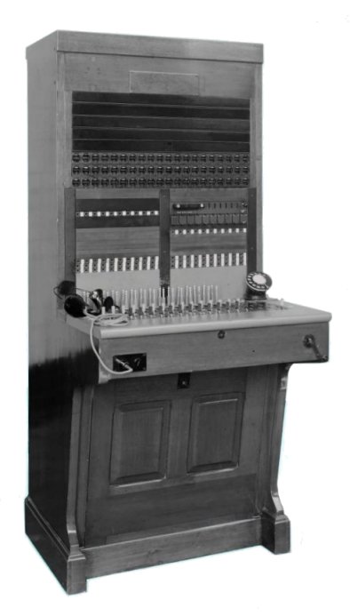 Switchboards N 1070 have been introduced for use, in place of Switchboards
AT 3796, where the extension or exchange line resistances are in excess of the
signalling limits for Switchboards AT 3796. They supersede for new work Switchboards AT
3796 modified to Diagram N 1096. These latter switchboards, while they increase the extension
to extension signalling resistance limits, do not give any increase in the exchange to
PBX, or exchange to extension, signalling-resistance limits which, for the AT 3796
switchboards, are lower than for other types of PBX. Switchboards N 1070 have been introduced for use, in place of Switchboards
AT 3796, where the extension or exchange line resistances are in excess of the
signalling limits for Switchboards AT 3796. They supersede for new work Switchboards AT
3796 modified to Diagram N 1096. These latter switchboards, while they increase the extension
to extension signalling resistance limits, do not give any increase in the exchange to
PBX, or exchange to extension, signalling-resistance limits which, for the AT 3796
switchboards, are lower than for other types of PBX. The N 1070 -
10+60(180) is shown pictured to the right.
Physical Design
The outward appearance, face-equipment layout, etc. of the new switchboard are identical
with that of Switchboards AT 3796.
Equipment, Capacity, Dimensions and Weight.
The Switchboard N 1070 is issued in the same three sizes as Switchboards AT 3796, viz. 10 +
30(65), 10 + 50(65), 10 + 60(180), each size being approximately 30lb heavier than the weight quoted in
TI E4060 for the equivalent size of AT 3796 switchboard.
Facilities
The facilities offered by the Switchboard N 1070 are similar to those described in TI
E4060 for Switchboards AT 3796 with the exception that only the first five cord circuits
are wired for night service working.
Diagrams
Cord circuit - N1070
Wiring diagram (all circuits) - LD 133
Circuit Details
The cord circuits give "divided feed" working on extension to extension and
extension to private circuit calls, but revert to through-signalling conditions on
exchange line connections. Basically, the cord circuit for the N 1070 type switchboard is
similar to that for the AT 3796 type and, for signalling purposes, the limiting factor is
the current requirement for the satisfactory operation of the supervisory indicators In
the cord circuit, i.e. 30ma. The extended limits on exchange calls have been obtained as
follows:-
(a) Exchange to PBX calls
The local transmission bridge is cut out on the operation of
relay AS to earth on the exchange line jack sleeve, and a loop. is offered to the
exchange. The resistance of this loop is the resistance of the bridging coil (L2) and
supervisory indicator only and is thus 160 ohms less than the loop offered by the
Switchboard AT 3796.
(b) Exchange to extension calls
The supervisory indicator on the extension side of the
cord circuit is operated to the PBX battery when the extension answers and, after
operating, holds to the public exchange battery. The contacts of relay CS prevent the
extension circuit being shunted by the bridging coil (L2) before the extension answers, at
which point the circuit is switched through and the bridging coil is disconnected. By this
means, satisfactory operating current for the supervisory indicator is obtained with a
longer extension circuit than is possible with the Switchboard AT 3796 modified to Diagram N
1096. Apparatus required
Box Connexion No. 3A.
Headset No. 1.
Mounting Dial No. 9.
Dial, Automatic No. 14.
Case No. 9.
Glasses No. 21A (in the case of a blind operator). Drawings -
63382 and 76462. Specifications - S327, S428 and S429.

|