RECEIVER WATCH No. 8T | |||||||
|
An extract from Receiver, Watch No. 8T A watch receiver has been developed for use with 700-type telephones. A feature of the new receiver is that it incorporates a gravity switch so that there is no unnecessary loss of received power when the watch receiver is not in use. As part of the modernisation program of subscribers' apparatus, a new and more efficient watch receiver (Receiver, Watch, No. 8T) has been introduced. It is provided as an addition to a standard 700-type telephone instrument when a second receiver is required, either for use in noisy situations or to enable a second person to listen, e.g. to make shorthand notes, and is hung on a small bracket projecting to the rear of the telephone. This bracket, which is of stainless steel, replaces the right-hand escutcheon plate in the cradle rest. The complete watch receiver consists of two mouldings to encase the receiver capsule, a stainless steel eye to hang it on its hook, and a coiled, extensible, plastic covered cord. The case is a one piece moulding in methyl-methacrylate with a moulded thread to accept the earcap, which is the standard item as used on the telephone handset. The cord entry socket is moulded to provide the same type of bayonet fixing for the cord grommet as that used on the handset, although reduced in size. The receiver capsule is the same type as that used in the standard handset (Inset Receiver No. 4T), and since it is connected in parallel with the existing receiver in the handset the available received power (apart from the slight mismatch loss) is shared equally between them. To avoid unnecessary loss when the watch receiver is not being used, and to prevent it emitting received speech when on its hook, the eye has been designed to provide a gravity switch within the watch receiver, the weight of which operates the switch. The eye, instead of being fixed rigidly to the outside of the case as in earlier designs, passes through a slot in the case and is extended to form a slide-bar which is free to move longitudinally for about 1 in. It is normally drawn into the case by a hairpin spring, but when the watch receiver is hung upon its hook its weight overcomes the force of the spring and the slide-bar is partially withdrawn from the case, i.e. when the eye engages with the hook the watch receiver slips down the slide-bar. This movement of the slide-bar operates the gravity switch. The inner end of the slide-bar is wedge-shaped and positioned between two nylon rollers on the ends of two wire contact-springs mounted in the pillars for the cord termination. The two contact-springs bear upon two special nuts on the receiver capsule to make electrical contact. When the slide-bar is partially withdrawn the rollers ride up the two inclined planes and the springs are lifted off the terminal nuts on the receiver so interrupting the circuit. As these contacts are not "wetted" by the flow of a direct current and heavy contact pressures cannot be obtained to operate the gravity switch because of the small force available from the weight of the receiver, both the terminal nuts and the wire springs are gold plated to provide reliable contacts. Introduced around 1964 Made originally by Standard Telephones and cables Ltd and later by A.P. Besson. Available in the colours: Ivory, Black and Grey. Drawing - 91784. Specification - S757
ENGINEERING INSTRUCTIONS STATIONS RECEIVER, WATCH No. 8T Description and Installation Introduction Description Use Termination First supplies of the Cord, Instrument, No. 2/145AK, 7in. will not be provided with cord grommets but will have a strain cord. Maintenance
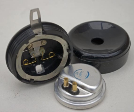
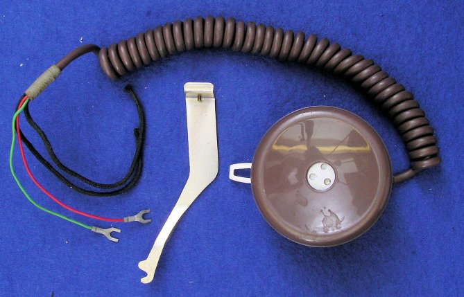
Receiver, Watch, No. 8T - Component parts
The hook bracket shown in the above picture is for use on
Telephone No's 740, 746 and later. |
|||||||
Last revised: July 23, 2025FM |