|
Click here for Overhead Construction Menu
P.O. ENGINEERING DEPT.
ENGINEERING INSTRUCTIONS
LINES
OVERHEAD
E 3080
Issue 1, 9.11.38
WIRING
Terminating
1. General
This Instruction describes the standard arrangements to be adopted in
terminating open wires.
2. Definitions
-
Terminating a line-wire consists in fixing it rigidly to an
insulator so as to maintain the tension required. Before tension is taken by the
wire at the terminal insulator, the free portion of the wire is passed round the
insulator to form a loop, and the "termination" is completed by securing the
wire as described in this Instruction.
-
Single termination is the term indicating the termination of a wire on one
side only of an insulator. The term is applied both to terminations at the ends
of a wire and to terminations at intermediate points where the wire is made-off
once only to an insulator, e.g. at a transposition cross.
-
Double termination is the term generally used to denote the termination of:-
i) a single wire in each groove of a double-groove insulator, with a jointless
bridging loop (or "bow") - a through termination, or of
ii) two wires, one in each groove, on a double-groove insulator and connected by
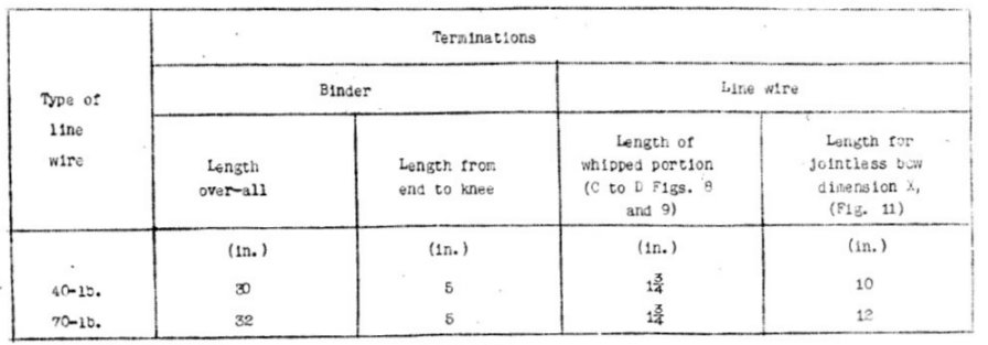
means of a bow formed by joining the tails together.
3. Terminating points
Terminations are essential at:-
-
terminal points, i.e. leading-in points, terminal and
distribution poles;
-
test points where the circuits are not led into a building or pole test-box;
-
intermediate poles where an alteration in the position of a circuit is
unavoidable (excepting points where such alteration is due to a difference in
arm capacity - in which case "transition poles" should be provided - see E
3040).
Line wires should also be terminated at the intermediate points enumerated in
paras. 4 and 5. Only in exceptional circumstances should wires be terminated at
other points.
4. Terminations at both ends of a span
Line wires should be terminated at both ends of the span at the following
points:-
-
Railway crossings.
-
Road crossings.
-
At crossings over power circuits, including the trolley wires of tramway or
trolley-vehicle systems.
-
Where an exceptionally-long span (100yds. or over) is unavoidable. These
terminations are required to obviate risk of the wire falling in the crossing
span in the event of a break occurring in adjacent spans.
5. Terminations at other intermediate points
Line wires should be terminated at other intermediate points, as follows:-
-
At transposition poles. (The longitudinal stays, provided at +-mile intervals
in accordance with D 3001, should be fitted at transposition poles wherever
practicable).
-
At least every mile in continuous sections of line, where terminations are
not required in compliance with para. 4 or 5 (a) (e.g. lines wired on the
"twist" system), to limit the effect of breakdowns. These terminating points
should coincide with points at which the longitudinal stays, specified in D
3001, are fitted i.e. the terminations should be on longitudinally-stayed poles.
If longitudinal stays are not provided in the first instance, the wires should
be terminated at poles where facilities for longitudinal staying exist.
-
At severe angles in the line, except where a pole is double-armed and the
wires are carried on straight spindles.
-
Where the erection of the wires is difficult ; e.g. over rivers or trees, and
over or on high buildings.
-
At the next pole to the terminal (or distribution) pole, where it is required
to divide the terminal stress between the first two poles on a line (see C 3301).
-
At changes of conductor gauge or material.
-
At junction poles ; i.e. where the wires branch off, either to another
pole-line or to a building.
All wires on the line should be terminated at points (a), (b), (c), (d) and (e).
Only the wires affected should be terminated at points (f) and (g), and these
terminations should be cut out if, and when, the wire is extended by wire of
identical gauge and material in the same relative insulator position.
6. Insulators
The circumstances in which the various types of insulator should be used at
terminating points are given in paras. 7 to 11.
7. At leading-in points, and at intermediate points where it is
necessary to connect the open wire to a lead, "Insulators, No. 16 or 17" should
be used.
8. For other single terminations (e.g. where a transposition
cross is to be inserted), insulators, of the type specified for through
positions of the circuit (see E 3035), should generally be used. Double-groove
insulators, with the wire terminated in the lower groove, should be used when
long open connexions are required, see para. 45.
9. At test points, "Insulators, No. 14" with "Fuses, Dummy, No.
1" should be used. The appropriate spindle for carrying these insulators
on arms bored for spindles and on saddles
(single-wire circuits) is Spindle No. 2".
10. At points where double terminations are required,
double-groove insulators should invariably be used. Appropriate sizes for
various conditions of use are enumerated in E 3035.
DOUBLE TERMINATIONS ON
SINGLE-GROOVE INSULATORS ARE STRICTLY PROHIBITED.
With such practice, chafing is
liable to occur between the two wires in the insulator groove, eventually
resulting in breakage; also, a broken bridge connexion may be masked, at the
time of breakage, by the rubbing contact of the two wires in the insulator
groove.
11. When it is necessary to run the open wires from a point on a
building to a leading-in point below, "Insulators No. 10" (in conjunction with
"Insulators No. 21") should be used, the wires between these points being
terminated on the insulator side-knobs. With the insulators firmly screwed down,
the side-knobs should be positioned so as to provide maximum separation between
the vertical drop-wires. With straight spindles, any adjustment necessary can be
made by turning the spindles in the bracket; with other spindles, by fitting
additional Rings, Insulator, No. 1.
TERMINATING LINE-WIRES OF 40 lb. AND 70 lb. PER MILE
12. The "twisted-sleeve" termination should invariably be used
for 40lb. and 70lb. cadmium-copper (or bronze) wires. This consists in the use
of a jointing sleeve in forming the terminating loop in the line-wire at the
insulator. The position of the sleeve relative to the insulator is such that the
loop, when not in tension, can be readily detached from the insulator. The
sleeve, when twisted with the wire, becomes virtually a joint and renders the
loop practically inextensible.
13. Discontinuance of the "wrapped-bight" termination
The twisted-sleeve superseded the wrapped bight as the standard termination for
40lb. and 70lb. wires in 1916. The wrapped-bight method, which consists in
doubling the line-wire back upon itself, taking the bight so formed round the
insulator neck and wrapping the end round both the standing part of the wire and
the tail, has, nevertheless, continued to be widely practised in some
localities,
chiefly because it lends itself to hand-tensioning of the wire. It will be seen
from E 3064 that hand-tensioning is not permitted. Use of the wrapped-bight
termination also constitutes an unauthorized departure from standard practice,
and should be discontinued.
14. Sleeves
The sleeves used for terminating are "Sleeves, Jointing, Nos. 14 and 16" and
these should be used as follows:-
a) "No. 14" 14½in. long, for 40lb. wire and
b) "No. 16" 1¾in. long, for 70lb. wire.
15. Tools
The tools required for making twisted-sleeve terminations are "Clamps, Jointing,
Nos. 1, 1A or 3" described and illustrated in E 3070. The small clamps (No. 3)
are most suitable for twisting the sleeves used in terminating 40lb. and 70lb.
wires. The detailed instructions given in E 3070 regarding the avoidance of the
use of faulty clamps and their removal from service, etc., apply equally to
terminating and should be carefully followed.
THE USE OF PLIERS FOR TWISTING SLEEVES IS PROHIBITED.
16. Looping around insulator
The wire which is to form the loop and tail of the termination should be free
from abrasions, bends, or other irregularities which would weaken it or prevent
its ready passage through the sleeve. It should be sufficiently long to provide
a loop of the size required (see para. 17) and, also, a tail for connexion to
the tail of the other termination or to the pole-lead, see paras. 24 and 25. To
form the loop, the sleeve should be pushed on to the standing part of the
line-wire, and the free end of the wire passed round the insulator groove and
brought back, through the sleeve, alongside the standing part. The sleeve should
then be moved into position, see para. 17; when terminating a regulated section,
the free end should be pulled at the same time so that the wire may be as tight
as possible between the regulating tool and the insulator.
BENDING THE FREE END AT THE END OF THE SLEEVE TO LOCATE THE
SLEEVE UNTIL IT IS TWISTED IS PROHIBITED.
NOTE:- When grease-packed sleeves are used (see para. 26) the
sleeve should be pushed on grease-filled end first, to ensure distribution of
the grease throughout the sleeve.

FIG. 1
POSITION OF SLEEVE RELATIVE TO INSULATOR
17. Size of loop
To avoid sharp bends at the sleeve and to ensure that the loop is sufficiently
large to allow it to be slipped off the insulator without further bending at the
sleeve, the distance between the sleeve and the insulator (see A in Fig. 1) must
not be less than the diameter of the insulator at the bottom of the groove, see
Fig. 1 (B). Generally, dimension (A) should be equal to (B); when terminating on
"Insulators, Nos. 16 and 17" and on the lower groove of No. 14, however, it is
desirable for dimension (A) to be made slightly greater than dimension (B) ;
this will facilitate the passing of the loop over the upper portion of the
insulator, which in these cases is, comparatively, of greater diameter. The
distance between sleeve and insulator, in relation to the various insulators,
illustrated in E 3035, can be obtained from Table 1.
TABLE 1

18. Twisting
The clamps (see para. 15) should be fixed so that their outer sides are flush
with the ends of the sleeve. In making the twists, the precautions and
instructions relating to the twisting of sleeve joints, detailed in E 3070, and
the instructions given in paras. 19 to 22, should be carefully observed.
19. Number of twists
Each sleeve (both with 40lb. and 70lb. wire) should be given 12 twists, see Fig.
2. If fewer twists are made, there is a distinct likelihood of the wire slipping
through the sleeve, whilst if more are given the sleeve may be fractured and/or
the wire overstrained.

FIG. 2
TWISTS IN SLEEVE TERMINATION
20. Avoidance of twists in short lengths of wire
Breakages are likely to occur if twists are made in short lengths of wire. The
clamp nearer to the point at which the wire is fixed in position should,
therefore, be held stationary, the twists being made by rotating the clamp at
the other end of the sleeve. Thus:-
-
when terminating a wire before it is pulled up, the loop may remain on the
insulator
if the clamp next to the insulator is held still and the other clamp rotated.
(The twists imparted to the wire of the span can be taken out by reversing the
coil, or by detaching the loop from the insulator after the clamps have been
removed).
-
when terminating after regulating, the clamp nearer the regulating tool
should invariably be held stationary, the twists being made from the opposite
end of the sleeve, WITH THE LOOP DETACHED FROM THE INSULATOR.
21. To remove the loop from the insulator, first ensure that the
sleeve, with the clamps affixed, is in the correct position relative to the wire
and the insulator. Then slacken the wire as required between regulating tool and
insulator by turning the ratchet drum, and lift off the loop, one side at a
time, taking care not to shift the sleeve along the wire. In the case of
insulators fitted with covers (Insulators, Nos. 14, 16, 17 and 21), the cover
should be off the insulator when the loop is being removed or replaced.
22. When the twists in the sleeve are made from the end nearer
the insulator, a cross in the loop results, as shown in Fig. 3. On no account
should the loop be twisted to take out the cross ; loops as shown in Fig. 4 are
produced when the twists are made from the end of the sleeve remote from the
insulator.

FIG. 3

FIG. 4
23. Treatment of free end ("tail")
In replacing the wire on the insulator, the tail, at the sleeve, should be at
the side on which it is to be taken to the insulator cavity or joined to the
other tail, see para. 43. This will avoid crossing the wire of the span, and
chafing can thus be prevented. When forming the connexions, the precautionary
instructions given in paras. 42-45 should be closely observed.
24. Connexion to pole-lead
Where connexion to a pole-lead is required, 40lb. tails should be taken direct
to the insulator cavity, as shown in Fig. 5. The tails of 70lb. terminations
should be shaped as shown in Fig. 6. Jointing should be as detailed in E 3070
and G 3001.

FIG. 5
TERMINATION FOR CONNEXION TO POLE- LEAD - 40lb. WIRE

FIG. 6
TERMINATION FOR CONNEXION TO POLE-LEAD - 70lb. WIRE
25. Connexion to another termination.
Where a tail is to be connected directly to the tail of another termination,
they should be brought together midway between the terminations, and jointed in
accordance with E 3070. The bows of double terminations should be on a level
with the terminations and should be shaped as shown in Fig. 7.

FIG. 7
DOUBLE TERMINATION - 40lb. AND 70lb. WIRE
26. Prevention of corrosion
Grease-packed sleeves. As a protection against corrosion, which is liable to
occur when moisture collects in the cavities at the ends of a sleeve, petroleum
jelly or other heavy grease is now being inserted in sleeves before issue, The
grease, apart from a thin film on the inner walls of the sleeve, is concentrated
at one end only ; reliance has, therefore, to be placed on the passage of the
wire through the sleeve from the grease-filled end for the sealing of the other
end, see para. 16. When the sleeve is twisted, the grease exudes and coats the
ends of the sleeve and the adjoining wire; no other treatment is necessary when
grease-packed sleeves are used.
27. Use of paint
When the sleeves used for terminating are not grease-packed (see para. 26), the
sleeve make-off should be treated with "Paint, Black, for Ironwork". The
surfaces of the wire and sleeve at the ends of the latter should be completely
coated, the paint being well worked into the cavities. It should be applied when
the surfaces are quite dry.
TERMINATING LINE-WIRES OF 100lb. OR MORE PER MILE
28. Method of terminating
All open wires of 100lb. (or more) per mile should be terminated by looping the
wire closely around the insulator and making-off by means of a length of
annealed binding wire, referred to in this Instruction as the binder.
29. Avoidance of joints at intermediate terminating points
An advantage of the binding-wire make-off is that, at intermediate points where
the line-wire will itself form the connexion between the terminations, the wire
can be terminated without destroying its continuity. During erection, therefore,
wire should not be cut at intermediate points as a matter of course for the
purpose of terminating. Where terminations (single or double) with jointless
connexions can be made without inconvenience, line-wire should be paid out and
erected without being cut, if otherwise practicable. For a transposition cross,
for example, the line-wire should be taken direct from the first single
termination to the second, one of the coils being passed under the other as
paying-out proceeds.
30. Binder
The binder used for making-off the terminations is as follows:-
-
Copper and cadmium-copper conductors of 100lb. or heavier
per mile ("Wire, Copper, Binding, 50lb.").
-
Cadmium-copper conductors of 40lb. or 70lb. per mile, 20lb.
copper wire, recovered locally from scrap P.C. cables.
-
Iron conductors, "Wire, Galvd., Binding".
The length of binder required for each type of conductor is given
in Tables 2 and
3.

FIG. 8
LOOPING LINE-WIRE AROUND INSULATOR
31. Looping around insulator
A "knee" should be formed in the line-wire in such a position that, with the
wire taut and central with the insulator, it fits up to the insulator groove,
see A in Fig. 8. To form the knee, the wire should generally be bent inwards,
i.e. towards the pole, so that the free portion B may be taken round the
insulator from the side nearer the pole, and the bow or tail formed on the
opposite side; see, however, para. 43. When the wire has been taken round the
insulator groove in the direction indicated, a second knee should be formed, see
C in Fig. 8, so that the loop will fit the insulator closely and the free
portion D lie alongside the standing part when the binding is being applied.
Where the termination is at the end of a section which has just been regulated,
the positions of the knees must be carefully determined to ensure that
the wire is taut between regulating tool and insulator, so maintaining correct
regulation.
TABLE 2
DETAILS OF TERMINATIONS
WIRES OF 100lb. PER MILE OR HEAVIER
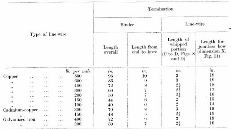
TABLE 3
32. Making-off
The termination should be made-off in the following manner:-
-
Form a "knee" in the binder (see A, Fig. 9) at the distance
from one of its ends specified in Table 2, and straighten the shorter portion.
-
With the longer portion towards that side of the insulator on which the bow
or tail is to be formed, place the short, straight portion (see B, Fig. 9)
under, and central with, the standing part and the free portion of the
line-wire, and hold these together near the insulator.
-
Take the free end of the binder round the insulator, keeping it under the
line-wire; see
C of Fig. 9.
-
Pull the binder tight, and pass it around both the free portion and standing part of the line-wire, embracing also the
straight portion of the binder. Continue the lapping closely and tightly for the
length specified in Table 2.
-
Bend the free portion of the line-wire D, Figs. 8 and 9, with an easy radius,
at right-angles to the standing part, and pull the straight portion of the
binder up in the fork thus formed see E, Fig. 9.
-
Extend the lapping to this point and complete the binding by lapping both
ends of the binder side by side around the main wire for five complete turns.

FIG. 9
MAKING- OFF TERMINATION

FIG. 10
TERMINATION FOR CONNEXION TO POLE-LEAD
WIRES OF 100lb. OR MORE PER MILE

FIG. 11
DOUBLE TERMINATION - MAKING JOINTLESS BOW
33. Treatment of free end ("tail")
The tails of the terminated wires should be dealt with as laid down in paras. 34
to 36 the precautionary instructions given in paras. 42 to 45 should be
carefully followed.
34. Single terminations
Where connexion to a pole-lead is required, the tail should be shaped as shown
in Fig. 10 and connected as detailed in E 3070 and G 3001. Where the tail is to
be used in forming a connexion to another termination (e.g. at a transposition
cross), it should, wherever practicable, be taken direct to the second
insulator, see para. 29: jointing a tail is dealt with in para. 37.
35. Double terminations
Except where a change of conductor gauge or material is made at a double
termination, the wire should generally be terminated without being cut, see para.
29. The jointless bow is made as follows:-
-
terminate the wire in the lower groove of the insulator. (It
will be realized from Fig. 11 that threading of the remainder of the coil
between the termination and the arm is necessary if the upper groove is used
first).
-
Form a knee in the free portion and place this against the insulator, see B
in Fig. 11. (The length of wire (X) required in the loop AB is given in Table 2
as a general guide; it is suitable for terminations in straight sections of
line, but some variation is necessary at angles).
-
Take the wire round the insulator, form the second knee (C) and apply the
binder, as detailed in para. 32, whipping the termination for the length
specified in Table 2, to point (D), Figs. 9 and 11.
-
Gripping the make-off at this point, turn the termination to its final
position, at the same time bending the loop to form an approximately
semi-circular bow.
-
Complete the binding as described in Para. 32.
Where it is more convenient to make-off the second termination in its final
position, form the knees (D) and (B) and the bow before looping the wire round
the insulator. (The distance between (D) and (13) can be obtained from the first
termination). A completed double termination is illustrated in Fig. 12.

FIG. 12
JOINTLESS DOUBLE TERMINATION
36. Jointed bows should be made by bringing the tails together
on a level with and midway between the terminations, and jointing as described
in para. 37. The bows should be approximately semicircular, as shown in Fig. 12.
37. Joints
Where a joint is necessary in a bow or other open connexion between
terminations, it should be made as detailed in E 3070. The twisted-sleeve joint
(see Fig. 15) is specified for wires up to and including 150lb. per mile, and
the Britannia joint (illustrated in Fig. 13), for wires of 200lb. per mile and
over. In the case of the former, the tails may be connected as shown in Fig. 14
where it is more convenient to make a "nib" joint than to twist a sleeve fitted
in the direction of the wire.

FIG. 13
DOUBLE TERMINATION WITH BRITANNIA JOINT
WIRES OF 200 lb. on MORE PER MILE

FIG. 14
DOUBLE TERMINATION WITH NIB JOINT
(150lb. WIRE ILLUSTRATED)
PRECAUTIONS
38. For the maintenance of correct regulation of line-wires and
freedom from faults it is important that the greatest care be taken when
terminating, and that the following instructions be carefully observed
39. Terminations to be completed before tension is applied.
Tension should not be applied to a termination before the make-off is finished.
When erecting wire, therefore, the termination at the beginning of a section
should be completed before the wire is pulled up; at the end of the section,
tension should be maintained by the regulating tool until the make-off is
completed and the wire is in its final position on the insulator.
40. Tightening insulator
Care should be taken to ensure that insulators on which wires are terminated are
so tightened that full advantage is obtained from the insulator ring (the rubber
washer fitted on the upper shoulder of the spindle, see E 3035). This should be
done before the load is taken at the insulator. With the insulator fully screwed
down, the completed termination should be rotated slightly on it in a
counter-clockwise direction. When the load is taken up, the termination will
return to the position of correct alignment. This will cause the insulator to
rotate and be firmly bedded on the insulator ring.
41. Position of wire on double-groove insulators. To maintain
equality of wire spacing, all the wires terminated on any one side of a pole
where double-groove insulators are used, should, where practicable, be made off
in the corresponding grooves of the insulators.
42. Open connexions between terminations should be symmetrical
and formed so as to provide good clearance from other conductors and from
fittings generally, and should be so rigid as to obviate the risk of contact.
The tail forming the bow or other connexion should not be bent sharply from the
wire of the span at the end of the sleeve or binding-wire make-off, and sharp
bends at other points should be avoided. No part of a bow or tail may be left in
rubbing contact with another part of the conductor.
43. Position of connexions
Connexions should be arranged so as to be out of the way of workmen, wherever
possible. The bow or tail should generally be at the side of the insulator
remote from the pole, where it is least liable to damage. For transposition
crosses, however, the tail should leave the make-off at the side nearer the
other wire of the pair, as shown in Fig. 15.
44. Bows
There should be sufficient wire in a bow to provide for jointing, should it be
necessary to cut the bow for testing purposes at a later date; in the case of
sleeve terminations (40-lb. and 70-lb. wire), care should be taken not to make
larger bows than is necessary for this. To avoid chafing, the tails should not
be looped round the insulator when making a jointed bow.
45. Long connexions. Where it is preferable to
connect terminations more than, say, 18in. apart by means of bare wire instead
of using cable, double-groove insulators ("Insulators, Nos. 7 or 4") should be
fitted and a separate "bridge" wire terminated, by the binding-wire method
(see paras. 30 to 32), in the upper grooves. Bows should be formed connecting
the bridge wire with the span terminations. Long connexions without this support
are insufficiently rigid and are likely to fail at their junction with the wire
of the span, where the effect of vibration in them is concentrated. Light-gauge
wire should not be used for long connexions wire of not less than 150lb. or
200lb. per mile (depending on length of bridge-wire) should be used.

FIG.
15
SINGLE TERMINATIONS AND ARRANGEMENT
OF CONNEXIONS FOR TRANSPOSITION CROSS
46. Disposal of scrap wire
When terminating, care should be taken to comply
with the instructions contained in A 0201 for the disposal of scrap wire.
|