HOUSE EXCHANGE SYSTEM (HES)
| |||||||||||||||||||||||||||||||||||||||||||||||||||||||||||||||||||||
Introduced around 1965 and made by Ericsson (ETL). HES 4 diagrams (ZIP) TELECOMMUNICATIONS INSTRUCTION HOUSE EXCHANGE SYSTEM No. 4 1 GENERAL
2 DEFINITIONS Non-Multiple Extension Main Station 3 CAPACITY OF INSTALLATION 4 EXTENSION PLAN ARRANGEMENTS Extension telephones cannot be associated with multiple stations, and it is not possible to work two multiple station telephones in parallel. 5 CONNECTION TO PUBLIC EXCHANGE The HES No. 4 is not suitable for shared service. 6 LAMP SIGNALS 7 EXCHANGE CALLS All Telephones, Intercom, No. 4/.... are fitted with standard magneto bells and up to five bells in series may be rung simultaneously from the public exchange except where the ringing supply is from a low-power source, e.g. a vibrator, when only one or two bells may be rung; see also para 13. For incoming exchange call ringing at non-multiple extensions see paragraph 9. (b) Incoming to Private Circuit (c) Outgoing from Multiple Stations (d) Outgoing from Non-Multiple Extension (e) Exchange Service Restriction or Prohibition (f) Main Station Control (g) Transfer Facility On installations with two exchange lines, a multiple station may hold a call on one exchange line while transferring a call incoming on the other line. The main station must assist in the transfer of exchange calls to or from non-multiple extensions or multiple stations with restricted facilities. During the transfer of an exchange call from one multiple station to another, the change of the exchange line lamp from flashing to a steady glow indicates that the receiving station is ready to accept the call. Pressing the exchange line release R button at the transferring station completes the transfer of the call, and this may be visually confirmed by the station engaging lamp, which dims at the transferring station and glows at the receiving station when transfer has occurred. (h) Hold Facility (j) Exchange Line Engaged (k) Secrecy and Monitoring 8 LOCAL INTERCOMMUNICATION CALLS Independent calls between stations in pairs, up to the capacity of the system may proceed simultaneously without mutual interference, but they are not secret and a station may break in by calling one of the engaged stations. (b) Calling a Station Engaged on an Exchange Call If the called station is a non-multiple extension the buzzer signal is given only when the exchange line is engaged speaking, not during hold conditions. Private circuits cannot hold or transfer exchange calls, and a buzzer signal will always be received when a private circuit is engaged on an exchange line call. (c) To Allow a Multiple Station to Call a Multiple Station Engaged on an Exchange Call (d) Multiple Station Calling Non-Multiple Extension or Private Circuit (e) Non-Multiple Extension Calling Multiple Station (f) Non-Multiple Extension Calling Non-Multiple Extension or Private Circuit (g) Private Circuit Calling Multiple Station (h) Private Circuit Calling Non-Multiple Extension or Private Circuit (j) Conference Calls Any non-multiple extension or private circuit, with the assistance of the main station may call all, or any number of other multiple stations, non-multiple extensions and private circuits, and then speak to them simultaneously. 9 NIGHT SERVICE TO NON-MULTIPLE EXTENSIONS Exchange service continues to be available at all stations and intercom calls are not affected by night service conditions. 10 NIGHT SERVICE TO PRIVATE CIRCUITS 11 ASSOCIATION WITH A PBX (a) An extension from a PBX may be connected as an exchange line at the HES No. 4. All facilities available to PBX extensions including operator recall, are also available to HES No. 4 stations. Mixed connections i.e. one exchange line and one PBX extension, are not permitted on installations with non-multiple extensions, due to line identification difficulties on outgoing calls from these extensions. (b) Subject to satisfactory transmission, a HES No. 4 non-multiple extension may be terminated as an exchange line or private circuit on the distant switchboard. Exchange calls can be extended only from the HES No. 4. (c) A Relay-Unit Q524 fitted in place of a multiple station and terminated at the PBX as an extension will usually provide all normal inter-switchboard facilities between a HES No. 4 and a PBX. (d) An HES No. 4 installation may be connected to another HES by private circuit, using a Relay-Unit Q524 fitted in place of a multiple station. The extension of exchange calls over a connecting circuit is not normally allowed. 13 EXTENSION BELLS AND BUZZERS One additional magneto bell may be provided at a non-multiple station for intercom signalling purposes. Loud sounding bells or buzzers may also be provided (see C3036). 14 TELEPHONES WITH HEARING-AID HANDSET 15 STD FACILITIES Formerly EI Telephones, Stations, Q1015 TELECOMMUNICATIONS INSTRUCTION HOUSE EXCHANGE SYSTEMS Nos. 3 AND 4 1 SCOPE OF INSTRUCTION
3 TELEPHONE, INTERCOM, No. 3/1 The moulded base (a standard item) is fitted with a special gravity switch and has been coded Part 4/DBA/107. Fitted between the gravity-switch pillars in a sub-assembly known as a Switch Composite, No. 1A, which consists of a spring contact unit wired to a Strip, Connection, No. 155B, the assembly having seven flexible spade-ended leads for connection to the telephone circuit. The contact unit is held in position between the gravity-switch pillars by four screws and the connection strip is held at the rear of the pillars by two locating pins and a spring clip. The plungers and spring contacts located in positions C and D of the latch- plate assembly form the intercom signalling circuits. The spring contacts and plunger in position B are contacts KX of the exchange line circuit, and these may be released either by replacing the handset or by pressing any one of the four buttons in positions C and D. The spring contacts in position A which are adjacent to position B, are contacts KH and these also operate when contacts KX are operated, but they can only be released by replacing the handset; these form the hold circuit of the exchange line. The remaining spring contacts in position A control the magneto bell cut-off or additional facilities. These springs are operated by a special plunger which is fixed to the latch plate by a bracket. The spring assembly is illustrated in Diagram Q 422 and the button arrangement is shown in Diagram Q424. Fixed on the sides of the gravity-switch pillars are two Lamp-fittings, No. 16 (incomplete); viewed from the front of the telephone, the fitting on the left-hand side contains a Lamp No. 26H which provides the red lamp signals for the exchange line, whilst in the fitting on the right-hand side is a Lamp No. 26 which provides the engaged signal for the intercom circuit. The d.c. buzzer for intercom calling is fitted onto the cord grommet frame and the complete assembly has been coded Buzzer No. 2B-2. The telephone is fitted with a Cord, Instrument No. 20/03AJ, ..., 72in which is terminated with the multiple cables onto a Block, Terminal, No. 37. The telephone is normally fitted with a Handset No. 3. The CB telephone has a Dial, Automatic, Dummy, No. 6A, The complete circuit of the telephone is shown in Diagram Q422 and the wiring of the Switch, Composite, No. 1A only in Diagram Q423. The instrument cord and cable connections for the telephone are shown in Diagram Q424. The telephone is available in black, grey and ivory. 4 TELEPHONE, INTERCOM, No. 4/1 The telephone mechanism is mounted on a metal base and is enclosed by a moulded plastic cover (Part 1/DCO/683). The telephone when issued is fitted with a Handset No. 3 and a Connector No. 1046A. The overall dimensions of the telephone are approximately 11.25in (285mm) x 6.75in (170mm) x 4.75in (120mm) high. Above the front sloping face of the cover containing the dial aperture, is an almost horizontal face in which is a rectangular aperture for the press-buttons of the key unit. Over the rectangular aperture and surrounding the press-buttons is a separate escutcheon which is sprung into place and clips onto the metal face of the key unit. This escutcheon contains the station identification labels with their clear plastic covers and the lenses for the exchange line lamps. The labels and plastic covers are removed by pressing at the end of the plastic cover with the blunt end of a pencil or similar object; this causes the middle to bow upwards where the cover and label may be gripped and pulled gently upwards. If the label does not rise with the cover it may be eased up by inserting a pin at the middle by the side of the label and levering gently upwards. The escutcheon is removed by inserting a thin blunt edged blade, or finger tip under the chamfered edge at the back and springing off the rear clip, then lifting upwards to release the front spring clip. In front of the handset rest there is provision for four press-buttons which are used to control the bell cut-off facility and any additional facilities that may be provided. The telephone cover is fixed by two screws in the handset rest and by a screw in the front of the dial mounting. The press-buttons are in two rows, from left to right there are the two ivory exchange line buttons engraved 1 or 2, two smaller ivory exchange line release buttons engraved R; ten grey press-buttons for signalling and speaking to other stations over the intercom circuits, and the single ivory conference button engraved C. At the front of the base are two bell gongs, over which Relay-units Q527 and Q528 (see paragraphs 18 and 19) may be mounted as required. The magneto bell is a Bell No. 59A with long flexible leads and has been coded Bell No. 59A-2. Behind the bell and across the base is a printed circuit board with the components of a standard 700-type telephone transmission circuit. The key unit is in two parts; a metal frame carrying spring-sets for the exchange lines and intercom circuits, and a press-button assembly. The metal frame screwed to the base of the telephone, carried on each side, the spring assembly of an exchange line and a printed board with spring contacts riveted to it, for intercom signalling and speaking. At the end of the frame near the exchange line spring contacts is a plunger assembly which operates on second and subsequent overpresses of an exchange press-button. The plunger operates a spring-set to provide operator-recall facility to either exchange line circuits. A second spring assembly inside the frame operates when the station press-buttons are overpressed and provides the intercom signalling condition. At the end of the frame near the conference button are a number of `polytags' carrying resistors associated with lamp circuits etc. On the top, near each of the four corners of the frame, is a lug which carries a Lamp-fitting No. 19 and a Lamp No. 41E. The press-button mechanism is held in the frame by a countersunk screw at each corner of the top plate. On the left-hand side of the base, beneath the dial mounting, is a metal bracket which carries a d.c. buzzer (Buzzer No. 2B-3) for intercom calling. Behind the key unit frame is a 72-way double-sided terminal block. On the top side is the telephone wiring; both soldered and screwed terminations. The instrument cord, a Connector No. 1046A, and any straps that may be required are terminated on the underside and these terminals are exposed by removing a cover plate from the base. Over the cord entries at the rear of the base is a metal bracket which carries the intercom transmission feed coil and its associated resistors and capacitor. The telephone is connected to the multiple cabling via a Box, Connection, No. 6A. The circuit and connector connections of the telephone are shown in Diagram Q540. The telephone is available in black, grey and ivory. The weight of the complete instrument is 8.1lb.
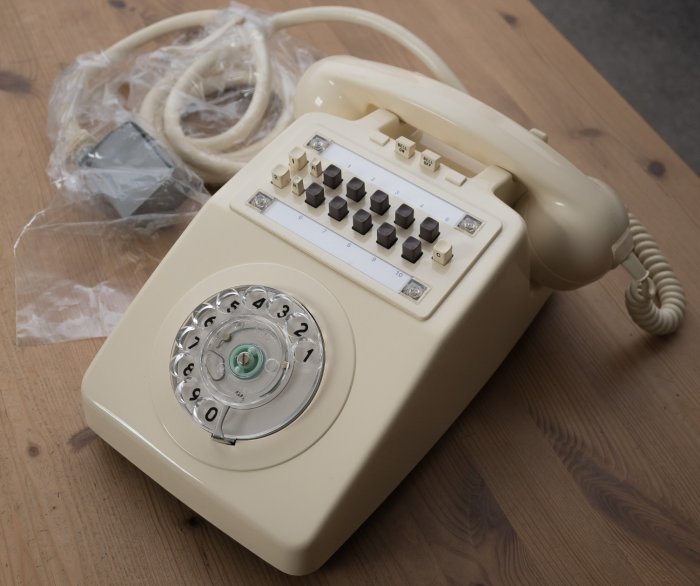
TELEPHONE, INTERCOM, No. 4/1
TELEPHONE, INTERCOM, No. 4/1 with case removed
TELEPHONE, INTERCOM, No. 4/1 with base plate removed and wiring terminals exposed
5 BLOCK, TERMINAL, No. 37... The Block Terminal, No. 37... consists of a moulded plastic base (Part 1/DBA/99) on which is mounted a terminal block (Part 1/DBL/91), containing 25 double-sided screw terminations the tablet and base being enclosed by a moulded plastic cover (Part 1/DCO/625). At one end of the cover is a cut-out for cord entry and at the other end are three knockouts for cable entry. The base has been modified to include a hole for back entry of cable and fixing holes for mounting the Block, Terminal, No. 37... over square type conduit outlet boxes, i.e. standard outlet boxes with 2.75in (70mm) fixing centres. 6 BOX, CONNECTION, No. 6A Mounted on the metal base is a Connector No. 203B55B, which is a 55-pin plug. Also fixed to the base on raised pillars are two 28-way terminal blocks (Part 1/DST/861). The inserts of the terminal blocks have screw terminals for multiple cabling on the front side, and solder terminals on the rear side which are wired to the pins of the Connector No. 203B55B. At the side of the connector is a bracket to retain the grommet of the telephone instrument cord (Connector No. 1046A). Also in the base is a hole for back entry of cables. The grey moulded plastic cover is held on by two fixing screws, and the sides contain knockouts for cable entry and a cut-out for the cord entry. Details of the wiring between the connector and terminal tablets are given in Diagram Q(L) 510.
7 BOX, CONNECTION, No. 7A 8 WALL-MOUNTED RELAY-UNITS Relay-unit Q405 is contained in a Case No. 131... which has a mounting surface of 12ins (305mm) x 4.5ins (110mm). All other wall-mounted units are contained in Case No. 133... which has a mounting surface of 12in (305mm) x 8.75in (220mm). Both cases extend 7.25in (185mm) from the mounting surface. Circuit components are mounted on a metal plate which is hinged to the baseplate and the wiring form from the components is terminated on a connection strip, which is fixed to the baseplate. Cable entry is via a hole fitted with a grommet in the baseplate. A clear space of 6ins (152mm) must be allowed on the left side of the units when fixing to the mounting surface. This space allows full movement of the hinged plate, with access to the wiring of the relays etc. A description of each wall-mounted relay-unit is given in paragraphs 9 to 14. 9 RELAY-UNIT Q 405 Wiring details are shown in Diagram. Q405 and in Diagram LD174, which is pasted inside the cover. .Cable connections are shown in Diagrams Q403 and Q404. When a HES No. 3 is working subsidiary to a switchboard with a low-power ringing source, it may be necessary to provide a local ringing supply, the output of which is controlled by relay contact RG2. Diagram Q417 shows details of alternative ringing arrangements when working a HES No. 3 subsidiary to a switchboard or when more than 'five bells are to be rung. The complete unit weighs approximately 5lb. (2.5kg). 10 RELAY-UNIT Q410 In this unit there is no spare contact on relay RG, and when a HES No. 3 with a non-multiple extension is worked subsidiary to a switchboard which has a low-power ringing source, it will be necessary to change relay RG. The relay should be changed for a Relay No. 9871, and the additional contact wired as shown in Diagram Q417, which gives details of alternative ringing arrangements. The relay RG must also be changed and wired to Diagram Q417, when more than five magneto bells are to be rung at any installation. The unit wiring and the multiple cable are terminated on a connection strip (Part 1/SST/71), with the cable connected to the screw terminals. Wiring details of the Relay-unit Q410 are shown in Diagram Q410 and in Diagram LD 175, which is pasted inside the cover. The complete unit weighs approximately 14lb. (6.3kg). 11 RELAY-UNIT Q415 Relay-unit Q415 contains a number of circuit elements, which may be strapped according to the type of signalling being used on the circuit. The wiring details of Relay-unit Q415 are shown in Diagram. Q415 and in Diagram LD180, which is pasted inside the cover. The connections required when using the Relay-unit Q415 are shown in Diagrams Q441 to Q447. Signalling limits for this unit are the same as for a Unit, Auxiliary Apparatus, No. 97 and are given in P1061. The unit wiring and multiple cables together with the required strappings shown in Diagram Q441 are terminated on two Strips, Connection, No. 121D mounted back to back; these are all soldered connections. The complete unit weighs approximately 15lb. (6.8kg). 12 RELAY-UNIT Q516 Current through each of the series connected exchange line engaged lamp circuits of a Telephone, Intercom, No. 4/1 is controlled by a transistor circuit. The transistor is mounted on a heat sink which also carries the associated resistors, capacitor and rectifier; this complete assembly has been coded Regulator No. 4A. The Regulator No. 4A is fixed by two screws to the hinged plate and joined to the circuit by three flexible spade-ended leads. Care must be taken to ensure that these leads are correctly connected otherwise the transistor may be seriously damaged. The regulator is adjusted during manufacture to pass 104mA (- or + 12 ma) under load conditions, and should any component become faulty, the complete regulator must be changed. Mounted on the baseplate of the relay-unit is a clip to hold a Connector No. 203C55C, which is a 55-way connector that has been provided with a number of straps between certain sockets, and is intended for use at multiple stations where a Telephone, Intercom, No. 4/1 has been disconnected for repair or replacement. By replacing the telephone socket with a Connector No. 203C55C the series circuits of the installation are maintained and service is continued at all other stations. The connections provided in the Connector No. 203C55C are shown in Diagram Q510. Wiring details of the Relay-unit Q516 are shown in Diagram Q516 and in Diagram LD192, which is pasted in the cover. The complete unit weighs approximately 12lb. (5.4kg).
13 RELAY-UNIT Q519 Circuits in the unit provide the non-multiple extension with most of the facilities of a multiple station; these facilities are fully described in C3031. A Strip, Connection, No. 121M provides the terminating point for the unit wiring, multiple cables and strappings as required. Straps that may be needed should be connected on the permanent wiring side of the Strip, Connection, No. 121M; and the multiple cables terminated on the opposite side. Details of the wiring are shown in Diagram Q519 and in Diagram LD195, which is pasted inside the cover. When a Relay-unit Q519 is provided, a Control-unit Q535 or Q537 (see paragraphs 21 and 22) is always fitted at the main station and the operation of the Relay-unit Q519 should be studied in conjunction with the operation of the Control-unit Q535 or Q537. Circuit elements and explanatory, notes are shown in diagrams in the 5... series. The complete unit weighs approximately 17 lb. (7.7 kg). 14 RELAY-UNIT Q524 The unit contains circuit elements which may be connected by strappings on the Strip, Connection, No. 121M, to terminate the circuit at the HES No. 4 according to the type of signalling to be used. The cable connections and straps required for various signalling groups are shown in Diagrams Q561 to Q567. Wiring details of the unit are shown in Diagram Q(L) 524 and in Diagram LD194, which is pasted inside the cover. Signalling limits for the Relay-unit Q524 are the same as for a Unit, Auxiliary Apparatus, No. 97 and these are shown in P1061. Straps should be connected on the permanent wiring side of the Strip, Connection, No. 121M and cabling should be terminated on the opposite side. The complete unit weighs approximately 17lb. (7.7 kg). 15 RELAY-UNITS MOUNTED IN TELEPHONES, INTERCOM These units consist of a Relay No. 16/... or Relay No. 23/6 mounted on a metal mounting plate which is secured over a bell gong. Other components may also be included, terminated on `polytags' pressed into the metal mounting plate. The various relay-units for fixing inside Telephones, Intercom, are described in paragraphs 16 to 19. 16 RELAY-UNIT Q408 The unit consists of a Relay No. 16/1 and two diodes (Valves, Electronic, CV 7040) on a mounting plate (Part l/DMO/102), and has spade-ended flexible leads for connection to the telephone circuit. Diagram Q408 shows the wiring of the unit and the connections within the telephone. 17 RELAY-UNIT Q409 The unit consists of a Relay No. 1612 wired with spade-ended flexible leads on a mounting plate (Part 2/DMO/102). Diagram Q409 shows the wiring of the unit and the connections within the telephone. Relay-Units No. 408 and 409 are mounted over the right-hand side bell gong. 18 RELAY-UNIT Q527 When exchanges service restriction applies to only one line the Relay-unit Q527 should be used and connected to the appropriate line. When both lines are to be restricted the Relay-unit Q527 should be connected to the line on position one of the telephone and a Relay-unit Q528 (see par 19) connected to the line on position two. The Relay-unit Q527 consists of a Relay No. 16/1 and two rectifiers (Valves, Electronic, CV 8308) on a mounting plate (Part 3/DMO/102), and has flexible spade-ended leads for connection to the telephone. Details of the wiring and telephone connections are given in Diagram Q527. The Relay-unit is mounted over the left-hand side bell gong. 19 RELAY-UNIT Q528 20 TWO-WIRE CIRCUIT CONTROL-UNITS AT MAIN STATIONS 21 CONTROL-UNIT Q535 The unit is contained in a Mounting D 92155 using a cover (Part 1/DCO/672, Grey), and a face plate (Part 1/DPL/2136). The 'EXCHANGE LINE' lenses are Caps, Lamp, No. 79C, Red and the 'EXTENSION' lens is a Cap, Lamp, No. 79C, White. The lamps used are Lamps No. 2-45V. The lamps and lenses are easily replaceable but other components are soldered in and should not normally be changed in subscribers' premises. The cord associated with the unit is a Cord, Instrument No. 18/04AJ, Grey, 72ins (1.8m) and this is terminated with the cabling onto a Block, Terminal, No. 37..., both must be ordered separately. Diagram Q535 shows the wiring details of the unit and Q1015 explains the facilities of the unit.
The unit is available in grey only. 22 CONTROL-UNIT Q537 The unit is contained in a Mounting D.92199 using a cover (Part 1/DCO/676, Grey) and a face plate (Part 2/DPL/2135). In addition to the parts contained in Control-unit Q535 (see par 21) the Control-unit Q 537 contains four key circuits which are used to connect non-multiple extensions and private circuits for intercom calls. When used at n installation with 2nd choice main station facilities, the Part 2/DPL/2135 is changed (see C3036). This unit is issued without a cord and Q3015 describes the conditions governing which cord should be fitted.. When a Cord, Instrument No. 18/04AJ, Grey, 72ins (1.8m) is fitted, a Block, Terminal, No. 37... must be used to terminate the instrument cord and cable. When a Connector No. 1046A or No. 1052A is fitted, a Box, Connection, No. 6A must be used to terminate the connector and cable. Diagram Q(L) 537 shows the wiring details of the unit and C3031 explains the facilities of the unit.
23 NON-MULTIPLE EXTENSION TELEPHONE
Telephone No. 710 fitted with buttons appropriate for a Non-Multiple Extension 24 EXTENSION BELLS ETC 25 ADDITIONAL RECEIVERS 26 LABELS When issued, Telephones, Intercom, No. 4/... are fitted with station identification labels (Labels No. 469/1 and 2) and these are described together with Labels No. 469 in C3036. 27 INSTRUMENTS CORDS AND CONNECTORS Cord, Instrument No. 20/03AJ, 72ins (1.8m) is normally fitted to Telephones, Intercom, No. 3/1. Cord, Instrument No. 25/04AJ, 72ins (1.8m) replaces Cord, Instrument No. 20/03AJ, 72ins (1.8m) when extra conductors are needed. Both cords have at one end 41ins (115mm) spade-ended conductor tails for Connection to the telephone, and at the other end, have the spade-ended tails formed into two rows of ten. Each row is held in position by strips of flexible plastic, which are moulded over the shanks of the spade terminals. The remaining five conductors of the Cord, Instrument No. 25/04AJ, ..., 72ins (1.8m) are left free. The plastic 'harness' assists in quick and accurate connection of the conductors to the Block, Terminal, No. 37... Each cord is stocked in three colours: black, grey and ivory, and in two lengths: 72ins (1.8m) and 120ins (3.0m). The Connector No. 1046A is normally fitted to a Telephone, Intercom,, No. 4/... and may be fitted to a Control-unit Q 537 if required. The Connector No. 1052A replaces Connector No. 1046A when. extra conductors are needed. Both connectors have at one end, 41ins (115mm) spade-ended conductor tails for connection to the telephone or control-unit. At the other end, soldered to the conductors, is a Connector No. 203C55A, which is a 55-way socket for connection to the Box, Connections, No. 6A. Both connectors are stocked in three colours, black, grey and ivory, and in two lengths, 72ins (1.8m) and 120ins (3.0m) Connectors, with 120ins (3.0m) cords are coded Connectors No. 1046B and No. 1052B. 28 CABLE 29 POWER EQUIPMENT 30 RINGING SUPPLY Formerly EI Telephones, Stations, Q1016. |
|||||||||||||||||||||||||||||||||||||||||||||||||||||||||||||||||||||
Last revised: September 24, 2025FM |