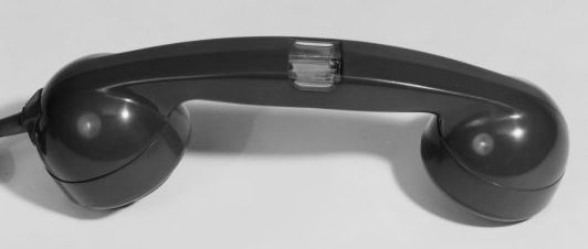
HANDSET No. 7 | |||||||
| Handset with neon light (Lamp No. 44A) for indication of incoming calls. Used with 700
type telephones. Fitted with Cord Instrument No 6/50AK. Colours: Black, Grey and Ivory. Drawing - 91781. Specification - S872. ETL Part - N9517D. ATM Part - L11394. TELECOMMUNICATIONS INSTRUCTION HANDSET No. 7 SCOPE OF INSTRUCTION
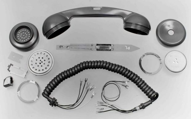
GENERAL DESCRIPTION (b) Lamp and Lamp Mounting (c) Cord, Transmitter and Receiver
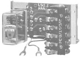
Handset No. 7 broken down into component parts ASSOCIATED APPARATUS The Lamp Signalling-unit No. 1 relay is connected in series with the bell and operates in unison with the incoming ring. The Lamp Signalling-unit No. 2 relay is connected initially in parallel with the bell and operates to the incoming ring. The relay is then disconnected from the bell circuit by its own contacts and is held operated by a local power supply until the telephone handset is lifted. In each case the relay is connected to a printed wiring board on which other circuit components are mounted. A connection strip is provided for terminating extra card conductors and for mounting voltage dropping resistors when these are required. When more terminals are needed for extension plans with Telephone No. 706, 710, 740 or 746, an additional connection strip, Part 2/DST/836, may be fitted on top of the strip provided but mounted the other way round. When an additional connection strip is needed in a Telephone No. 711 or 741 it should be bolted directly on either of the gravity-switch brackets. When fitted on some 74x type telephones where three capacitors 0.9pf are provided in the telephone circuit, it may be necessary to ease one capacitor slightly to one side to facilitate the fitting of a lamp Signalling-unit. Transformers Nos. 431A and 431B TYPICAL CIRCUIT ARRANGEMENTS (a) Exchange lines or PBX extensions where automatic ringing is derived from a ringing machine where there are no more than two bells and one lamp in series the lamp may be lit directly from the ringing supply, i.e. no local a.c. supply is required. As shown in Diagram N 1901 a resistor is connected in parallel with the lamp to extend its life by limiting the current flow and to restore the line capacitance condition for testing purposes. (b) Exchange lines or PBX extensions where automatic ringing is derived from a vibrator source, or from a ringing machine where more than two bells and one lamp are required the Handset No. 7 and a Lamp Signalling-unit No. 1 should be connected as shown in Diagram N 1901. The relay operates in unison with the incoming ring to energise the rigor, lamps and extension bells from a local a.c. supply. When several Handsets No. 7 are required to be connected to a PBX with vibrator ringing, the GM (Engineering Division) should consider whether it is more economical to replace the ringing vibrator by a ringing machine rather than provide individual lamp signalling units and transformers.
(c) Exchange lines or PBX extensions, where ringing is applied manually the Handset No. 7 and a Lamp Signalling-unit No. 2 should be connected as shown in Diagram N1901. The circuit is so arranged that the relay operates to the first period of ringing, is then switched away from the line to be held operated from a local a.c. supply which also energises the neon lamps via the relay contacts. The relay remains operated until the telephone handset is lifted, but the bell is left connected to the line and may still be rung from the switchboard. (d) Non-Standard Applications Where non-standard facilities are required particulars should be passed to GM (Sales Divn) for submission to THQ. LOCAL RINGING OR AC SUPPLIES Formerly EI Telephones, Stations, A1075 An extract from A 700-Type Telephone Handset Providing Lamp The Handset No. 7 incorporates a neon lamp visible through a clear window forming part of the handle. The lighting of the lamp provides a calling signal in addition to the sound of the telephone bell. INTRODUCTION HANDSET No. 7 The use of a filament lamp was rejected because of the possibility of damage by heat to the thermoplastic moulding and because of the fragility of the filament: a neon lamp is a gas-discharge tube and has neither of these limitations. Furthermore, neon lamps have a long life at a low current-rating and can, in many instances, be lit directly by the ringing current because they operate satisfactorily to a 60v or 75v a.c. supply. The handle of the Handset No. 7 was originally made by moulding the body and window separately and then cementing the two together. This process proved unsuitable for mass production, and a further examination of the problem resulted in the double moulding technique now employed. By this method the body is made in coloured ABS (acrylonitrile-butadiene-styrene) with an aperture left for the window. The window is afterwards moulded in place over projections in the body moulding which ensure that the window is kept in position even when the handset is deliberately distorted. The neon lamp is mounted on a printed-wiring board and fitted in the hollow handle so that the lamp is under the window, the printed-wiring board being inserted in the handle through the cord-entry hole. The moulded block that anchors the cord is normally cemented in place, but in the Handset No. 7 it is removable and is held in position by a spring clip contained in the transmitter cavity. This clip, in conjunction with the small synthetic-resin-bonded paper (s.r.b.p.) strip fitting over the terminals, also provides a location for the printed wiring board. Because an extra pair of conductors is always needed for the lamp connections a six-way extensible cord is supplied with the handset. CIRCUIT ARRANGEMENTS In U.A.X. or P.A.B.X. systems in which vibrator ringers are employed, the voltage available may be insufficient to strike the lamp in a Handset No. 7. For such systems a relay wired in a full-wave bridge-rectifier network is connected in series with the bell. The relay operates to the ringing current and the lamp lights to a local power supply connected via the relay contacts. Because neon lamps do not operate satisfactorily in series or directly in parallel, this arrangement is also used where more than one telephone with a Handset No. 7 is connected to a single automatic exchange line or P.A.B.X. extension. On manual systems the lamp lights when ringing current is first received, and it stays alight until the call is answered. This is effected by a relay connected across the bell; when ringing current is received the relay operates and is disconnected from the telephone circuit by its own contacts. Until the handset is lifted the relay is held operated to the local power supply, which also lights the lamp. In a similar way, the lamp-signalling units can be used to ring bells, if required. AUXILIARY APPARATUS The local power supply used with the lamp signalling units may be provided by one of the following: a 75v 162c/s or 25c/s ringing generator; 60v 25c/s ringing converter; a 75v 50c/s plug-in a.c. mains transformer. The latter consists of a transformer combined with a standard size mains plug and is available in two versions, known as Transformers No. 431A and 431B. It should be noted, however, that 50c/s current is not suitable for ringing extension bells. The Transformer No. 431A has a 15amp plug with round pins, and the Transformer No. 431B has a 13-amp plug with flat pins; the large size of the plugs gives stability to the units when they are inserted in the appropriate mains outlet sockets. Both primary and secondary windings are protected by fuses and are separated by an earthed screen; the laminations are also earthed. The transformers are supplied with a lead-out pair already connected to the low voltage output terminals to avoid having to dismantle the unit during installation. Connecting the handset to a 700 telephone This handset was designed to work with the original 700 type telephones: with 1000ohm bell ringers. The new plan working involves changing the ringer resistance to 4000ohms and this additional resistance will not allow the bells to ring as the neon has not struck. The original method is wiring can be found on Diagram N1901. The original N diagram shows the neon connected in parallel, across a resistor, in series with the bell. This method can be still used with the 3k3 resistor connected between Terminal 4 and Terminal 5, in a modified phone but this will probably only work if the bell ringer is 1k resistance and not 4k resistance (where the 3k3 resistor would not be required anyway). This explanation of how to wire a Handset No. 7 to a new plan 700 type was found on the web and I cannot guarantee it to work. With PST wiring it was found that the easiest way to get the neon in the handset to light is to exploit the unused 1.8uf capacitor between Terminal 9 and Terminal 7 with a suitable series resistor, found by experiment but usually between 1k and 4k Ohms, in one of the leads of the neon. The connections for the above are:-
|
|||||||
Last revised: July 30, 2025FM |