| |||||||||||||||||||||||||||||||||||||||||||||||||||||||||||||||||||||||||||
| Magneto Floor Switchboards Cordless
N563 shown pictured to the right. Enamelled cast-iron stand, matt polished woodwork with fibre-faced jack field. The connections are made by means of cordless plugs, and the jacks are mounted in rows varying in number, according to the size of the switchboard. Each row, parallel with the line indicators, represents a connecting circuit and has associated a clearing indicator, an operating key and two plugs. A key, connected to the generator, is fitted in each line circuit for calling purposes. Night bell, switch, micro-telephone, testing key and two spare plugs are provided.
N560 and N561 have the connecting circuits arranged vertically. N564 is replaced by N569 Taken from the Ericsson catalogue, edition 26 INTRINSICALLY SAFE SWITCHBOARDS Type N561A shown
Indicators are totally enclosed, push-button-restored disc type. They are surmounted by a white celastoid designation label. The push keys have stout metal tops and plungers. To simplify operating, alternate horizontal rows of keys are engraved black and red, respectively. A key and terminals for the connection of power ringing are included; the hand generator is in a separate metal enclosure attached to the underside of the switchboard. The operator's telephone circuit is incorporated in the board, and the moulded plastic handset has a vulcanised rubber cord with plug and jack connection. The form of anti-side-tone circuit used ensures satisfactory reception of speech even in noisy situations. The alarm bell, and batteries for bell and transmitter circuits are external. They are ordered separately and must be of approved type. Screw terminals are provided for the connection of Type N8656 Code Ringing Delay Units to the number of lines stated in the Table, and also for the connection of auto/magneto switching units. A gland for s.w.a. cable is normally supplied. The wires enter from below and connect to screw terminals on strips mounted on the rear wall of the case. If a different gland is required, the type and overall diameter of the cable being used must be specified. If cable is in conduit, the latter can be attached to the switchboard by locknuts. The table below lists the details and sizes of the switchboards available. Type N562A has two and Type N563A three hinged front plates. Circuit schematic and wiring diagrams are supplied with each board. Connecting wires are insulated with p.v.c.
Note: The height (18 in.) is inclusive of generator case Taken from the Ericsson Catalogue No. 60 |
|||||||||||||||||||||||||||||||||||||||||||||||||||||||||||||||||||||||||||
Last revised: July 24, 2025FM2 |
 ERICSSON
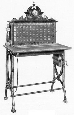 These switchboards are designed for use where larger ultimate capacity than
the Pyramid type, previously described, is required. They are arranged to give a limited
number of connections in order that the overall dimensions are not unduly large.
These switchboards are designed for use where larger ultimate capacity than
the Pyramid type, previously described, is required. They are arranged to give a limited
number of connections in order that the overall dimensions are not unduly large.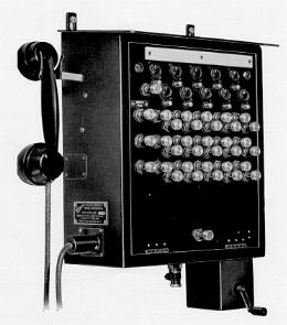 These are black finished all-steel switchboards designed primarily for use
in collieries but suitable also for oil installations. They may be used above or below
ground, the sloping reinforced roof which projects over the front of the board providing
protection against falling roof material and water. Mounting bars are attached, but the
board should be mounted on battens to allow free circulation of air and thus prevent
moisture collecting at the back and causing corrosion. The hinged front is secured at the
top by two recessed triangular-headed screws for which a key is supplied.
These are black finished all-steel switchboards designed primarily for use
in collieries but suitable also for oil installations. They may be used above or below
ground, the sloping reinforced roof which projects over the front of the board providing
protection against falling roof material and water. Mounting bars are attached, but the
board should be mounted on battens to allow free circulation of air and thus prevent
moisture collecting at the back and causing corrosion. The hinged front is secured at the
top by two recessed triangular-headed screws for which a key is supplied.