| ||||||||||||||||||||||||||||||||||||||||||||||||||||||||||||||||||||||||||||||||||||||||||||||||||||||||||||||||||||||||||||||||||||||||
| Battery Ringing Telephones RAILWAY TYPE N1200, N1201 and N1202
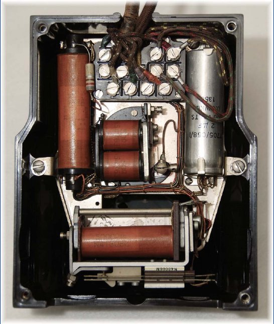
The N1200 is shown pictured to the right. Intended mainly for office use, the table set is arranged for systems requiring from one to three push-button keys the springs of which are wired to terminals which can be strapped to suit various operating requirements. The instrument, micro-telephone (with or without transmitter cut-off switch in the handle) and terminal block are of moulded Bakelite and interior components such as springsets, buzzer, condenser, induction coil, and relay when required, are mounted on a chassis which is readily removable as a unit. The 100 ohm buzzer is directly operated in single-button telephones and via the contacts of a 5000 ohm polarised or non-polarised relay in the 2 and 3 button sets, provision also being made in the local wiring for the fitment of a differential relay if required. Terminals are provided for connecting an external bell if desired. Supplied in Black only, with no tray, to the Railway Signalling Committee specification (RSC Spec. No. 1000). Overall dimensions 9 x 11 x 5 inches.
Taken from the Ericsson catalogue, edition No. 49
Click here for an article from the Ericsson Bulletin N1201 - Southern Region Diagram is E509-44 Click her for the diagram of the N1201 - Diagram N68795 (dated 1945) Click her for the diagram of the N1201C20 - Diagram N98236 Click here for diagram of the N1200N20T Figure 1 - Diagram N98692 Click here for diagram of the N1200N20T Figure 2 - Diagram N98692
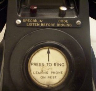
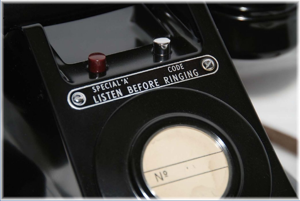
Additional Pictures
|
||||||||||||||||||||||||||||||||||||||||||||||||||||||||||||||||||||||||||||||||||||||||||||||||||||||||||||||||||||||||||||||||||||||||
Last revised: May 07, 2026FM2 | ||||||||||||||||||||||||||||||||||||||||||||||||||||||||||||||||||||||||||||||||||||||||||||||||||||||||||||||||||||||||||||||||||||||||
 ERICSSON
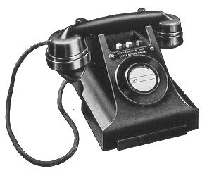 These instruments are specially designed for the battery signalling systems usually
preferred for railway telecommunication and combine neatness with durability and
efficiency.
These instruments are specially designed for the battery signalling systems usually
preferred for railway telecommunication and combine neatness with durability and
efficiency.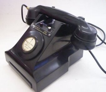


