BPO Dials, Automatic, No's 1 - 9 | ||||||||||||||||||||||||
| Lettering on dials Click here for an explanation of how dials work Information on later dials - Dial, Automatic No's 10 to 54. Dial labels - paper labels The text below is taken from many sources, some of which are:- TELECOMMUNICATIONS INSTRUCTION,
C MARKETING, INSTALLATION, 3 Internal, M0015, Issue 1, Sept 1971. DIALS, AUTOMATIC, No's 1 to 9
|
 |
 |
 |
| B Label No. 155 |
F Label No. 149 |
L Label No. 150 |

Brighton Dial
The second letter and any following number refer to the type of pulse wheel, shown below.
- Type A = 66.6/33.3 - used on standard GPO Strowger exchanges.
- Type S = 33.3% break for Grimsby, Stockport, Southampton, Hurley and Ramsey (Siemens Bros.)
- Type W = 18.5% break plus final break of not less than 92.5% of the total impulse period, for Dudley and Darlington (STC Rotary).
 |
 |
 |
| A | S | W |
Click here for
more information on the Brighton Dial
Early British dials
Prior to the introduction of the BPO No. 8 and 10 dials, each supplier had its own pattern and these were given numbers by the BPO as follows:-
- No. 1 Automatic Electric, used at Epsom and the Official Switch (London).
- No. 2 Variant on No. 1 used only on the test desk at Epsom.
- No. 3 Siemens Bros, used at Grimsby, Hurley, Ramsey, Stockport and Southampton.
- No. 4 Never issued.
- No. 5 Western Electric (S.T. & C. Co), used at Dudley and Darlington.
- No. 6 Redesigned version of No. 5.
- No. 7 Flameproof version of No. 3.
- No. 8 Prototype of the Dial No. 10.
- No. 9 Prototype of the Dial No. 10 when used on coin boxes.
History of early dial progression (by Jack Ryan)
In 1920 there were several trial exchanges operating on the public
telephone network. Each of these exchanges made use of proprietary
subscriber equipment which had been accepted for use by the GPO.
In November, 1922, the Engineer-in-Chief of the Post Office, Colonel Purves, recommended the adoption of the Step-by-Step system with the addition of the director for use by the Post Office.
Once adopted, this recommendation would standardise all switching equipment on the public network. The requirement of the GPO for standard interchangeable and interworking equipment was now clearly documented.
By this time the Standard Telephone was fairly well established but each exchange type used its own dial.
-
Dial No. 1 - introduced by ATM in 1912.
-
Dial No. 3 - introduced by Siemens Brothers in 1916.
-
Dials No. 5 & 6 - introduced by Western Electric from 1914.
The GPO required a standard dial for logistical if for no other reason. None of the existing dials could be made to emulate the operation of all the others so a new standard dial was required.
This standard dial was to supersede the four dials listed above and to achieve that, the following was required:-
-
It had to conform to the established mounting (ATM), form (Siemens Brothers) and operation (all).
-
The pulse cam had to be the low speed (approx. 1 revolution per second) type with interrupter teeth around its circumference to give the maximum flexibility in timing.
-
The pulse cam had to be interchangeable to support ATM ("A" cam), Western Electric ("W" cam) and Siemens Brothers ("S" cam) exchanges.
-
The inter-digit period was to be adjustable to take advantage of the shorter setup time between digits required on Western Electric exchanges (the finger stop location was to be adjustable).
-
The standard impulse was to be 66% break and 34% make (PO Research Department Report 1921).
The first standard dial, the Dial, Automatic No. 8, was released circa 1921 on the Telephone No's 105 and 124. The Telephone No. 124 superseded the Telephone No. 72 (ATM), the Telephone No. 76 (British WE), the Telephone No. 82 (Siemens Brothers) and others so that all manufacturers could now use the same pattern telephone and dial. It featured changeable pulse cams and an adjustable finger stop location.
Technical issues necessitated another change to the Standard Dial. To support telephone circuit changes designed to address problems of contact arcing, coherence and acoustic shock, the Dial, Automatic No 10 was released. The only change from the Dial No. 8 to the Dial No. 10 was the number of and configuration of the off normal contacts.
The Telephone No. 150, fitted with Dial, Automatic No. 10, was released around 1929.
With the introduction of the Dial, Automatic No. 10, most suppliers adopted this for telephones supplied to all customers, not just the BPO. ATM, however, favoured the Type 24 dial designed by Automatic Electric Inc of Chicago (introduced 1926) and supplied this to Hull Corporation and other private customers well into the 1960s. A variant of this was the ‘dimple dial’, using the same mechanism but a plastic finger wheel having moulded dimples instead of proper finger holes. These ATM dials were never adopted by the BPO, although many ATM Type 24 dials, taken from Hull Corporation Telephone No. 162's, were ‘brassed up’ in the 1970's and fitted to otherwise genuine BPO Telephone No. 150's.
The stainless steel fingerplates were brought out around 1936 (the first GPO picture showing a stainless dial is dated 1936). The stainless steel finger wheel also replaced the Bakelite finger wheel on the coloured Telephone No. 162. The Bakelite finger wheel was just not durable enough for every day use.
The first Dial, Automatic No.10 had oxidised finger plates matching the switch hook lever. The oxidised finger wheel was heavy, made of brass which was copper plated and oxidised black. The dial label centre was small. The finger plates were later just painted black until the introduction of the chrome finger plate.
Dials No. 1
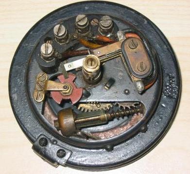
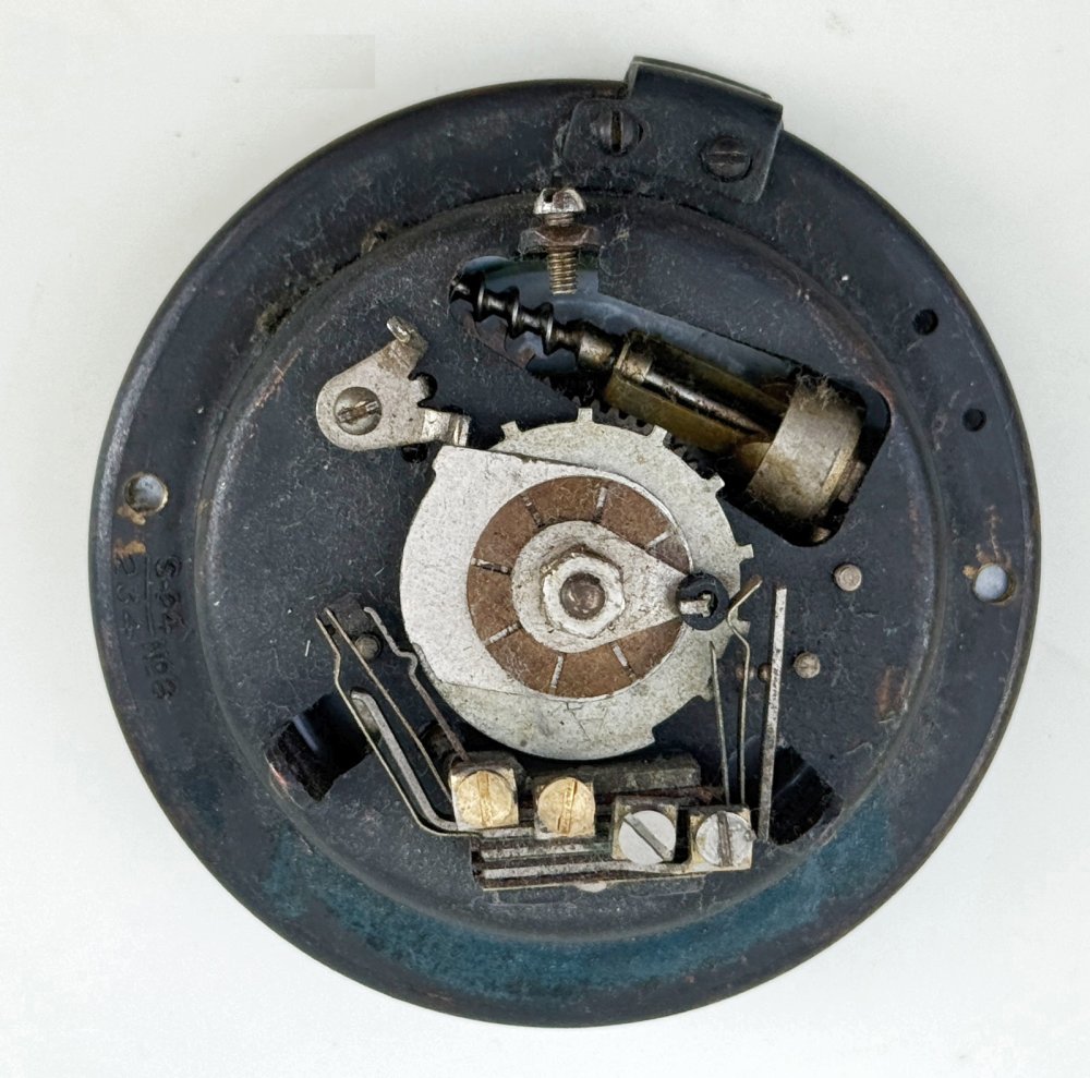
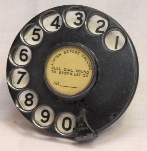
The first dial used in the UK (known as Dials, Automatic No. 1) is shown
below. This was used on the ATM Co's automatic switching system. A minimum pause is not provided in this dial. The impulse springs normally rest in contact due to their own resilience instead of being pressed into contact by an impulse wheel. Impulsing is effected by causing the wings of a fibre butterfly cam to pass between the springs, so separating them. When the wing of the cam leaves the springs they fall together to form the
"make" portion of the impulse. A ratchet, which can be seen in the side view, prevents the rotation of the cam while the finger plate is being pulled. The return motion of the dial is effected by a spiral spring (i.e., not a clock spring). It
can be seen that the method of operating the switching spring combination is not so robust as that of Dial, Automatic No. 10 and it was the undesirability of operating more than one spring set in this way which precluded the use of an instrument circuit such as the present standard
(Telephone No. 150). This dial was used on Telephone No.
55
and 72. Superseded by the
Dial,
Automatic No. 8FA.
Break period is .61 seconds.
The dial label is a Label, No 97 or 97A and can be found on Diagram A.T.733.
The dial number ring is Label No. 113.
ATM Part Number - T4207.
Adjustment instructions for these dials are contained in circular A.T. 6 dated July, 1919.
Diagram - A.T. 8.
Nicknamed the "Mercedes" dial due to the shape of the label retaining clip.
Click here for a break down of dial parts
 |
 |
| Front | Rear |

Dial No. 2
This dial is a variant of the Dial No. 1 and used only on the test
desk at Epsom exchange.
Dial No. 3
 The Dials, Automatic No. 3, which provides minimum pause and which was used with Messrs. Siemens earlier equipments at Grimsby, Stockport and Southampton. This dial resembles the No. 1 dial in that a fibre cam is used to interrupt the impulse circuit and also in the method of operation of the switching springs.
Used on Telephones No's 77 or
82. Superseded by the Dial,
Automatic No. 8FS.
The Dials, Automatic No. 3, which provides minimum pause and which was used with Messrs. Siemens earlier equipments at Grimsby, Stockport and Southampton. This dial resembles the No. 1 dial in that a fibre cam is used to interrupt the impulse circuit and also in the method of operation of the switching springs.
Used on Telephones No's 77 or
82. Superseded by the Dial,
Automatic No. 8FS.
With this dial a definite minimum interval between trains of impulses is secured. Where this is not provided. short trains of impulses, such as 1. 1. 1, may arrive before a free electing switch has been found. To effect this interval the dial switch is provided with two trains of gears, the governor train and the impulse train. The ratchet wheel driving the governor train. is fixed to the finger plate and driven thereby. The impulse train is driven by a pawl mounted on a disc, the disc being located between the driving wheels of the respective trains. The pawl referred to engages the internal teeth of the ratchet wheel, thus transmitting the drive to the disc and subsequently to the impulse train in one direction only. The disc is further provided with a slot, the ends of which engage a pin on the toothed wheel of the impulse train. so that the governor comes into action some time before the impulse train. When the dial is released the governor starts at once, but it is only after the pin has passed to the other end of the slot that the impulse train is operated and impulses begin. No matter how quickly the dial is operated, this interval must occur between successive trains of impulses.
The governor and the main spring have been made the subjects of special study and design, to give great regularity in the timing of the impulses. The impulse springs are normally held closed by the fibre, opening under their own tension. This assists greatly in securing exact pulsing.
Introduced in 1918.
The dial label is a Label No. 118 or No. 118A and can be found on Diagram A.T. 733.
The dial number ring is Label No. 124.
Adjustment instructions for these dials are contained in a mimeographed circular dated March, 1924.
Diagram A.T. 501.
Variants
Siemens Brothers called the Dial, Automatic No. 3 their Dial, Switch No. 1.
The Dial, Automatic No. 3 dial is a derivative of the Dial, Automatic No. 1 and like the Dial No. 1, is incapable of generating the pulses required for a WE Rotary exchange as the Rotary exchange requires the "last long pulse" and the No. 3 dial (and No. 1) is incapable of generating that. Because of this Siemens Brothers developed the Dial, Automatic No. 8, in which the pulse wheel was replaceable to suit other exchange types.
Click here for the Canadian Patent No. 229759
 |
 |
| Front | Rear |

Dial No. 3 front view
Dial No. 3 rear view

Dial No. 3 parts
Dials No. 5 & 6
These were produced by BTMC (Western Electric), their series
7000 dials. The Dial No. 6 had a back plate which allowed the
dial to fit the standard UK dial aperture. The Dial No. 6
superseded the Dial No. 5
Dials, Automatic No's 5 and 6 were used in association with the S. T. & C. (late Western Electric Co.) rotary system at Dudley and Darlington. The mechanism is totally enclosed. Externally the dial is unique in that the number ring rotates with the finger plate.
The huger disc is mounted on a shaft and held against a atop by a spiral spring. When displaced from normal the disc returns under the tension of the spiral spring, but does so at a predetermined and constant speed under the influence of a governor. A special loose disc at the centre is so fitted. that the finger disc may be moved forward as quickly as desired, the governor being disconnected.
The finger disc carries a series of small teeth and one large tooth, which operate in passing a contact lever: the contact lever opens a contact, included in the line circuit, but only on the return movement of the finger disc. The short interruptions of a train of impulses are always followed by a long one to mark the change over. The break period is .12 seconds.
In the Western Electric Co.'s system, a long interruption of the circuit at the end of a train of impulses allows a relay, made slow to energise, to energise and bring about the change-over to another register.
The No. 5 was fitted with 2 terminal dial, which consisted of impulse springs only, whilst the No. 6 was a 4 terminal dial where an additional contact set was added that short circuited the receiver, when the dial was in use.
With early installations, the impulses were sent by keys or push buttons, a plurality of keys being provided, one for each digit of the hundreds, tens and units. These proved unreliable, as the subscriber could not be depended on to depress a key the correct number of times, according to the digit.
Dial No. 6 was used on Telephones No's 65 (Mark 235) and 76 (Mark 235). Superseded by Dial, Automatic No. 8FW.
The dial label is a Label No 119 for Dial, Automatic No. 5 and 119A for Dial, Automatic No. 6. Both can be found on Diagram A.T.733.
The dial number ring for the Dial No. 6 is a Label No. 125.
Drawing (Dial, Automatic No. 6) - A.T. 319.
Western Electric called this the Dial No. 7006.
BTMC made a Dial No. 7010B which whilst looking similar to the No. 7006 was
actually a successor design.
 |
 |
| Dial No. 6 Front | Dial No. 6 Rear |
Dials No. 7
This was similar to the No. 3 dial but was modified to give an impulse ratio suitable for the A.T.M.
Company's system, and was enclosed to exclude gas. It was intended for use in mines, or where petrol was stored.
This dial was obsolete by 1928.
Dials Nos. 8 & 9
Dials No. 8
 Introduced
a standard dial it was designed
by Siemens Brothers. The Dial,
Automatic No. 8 is the prototype of
Dials, Automatic No. 10 and its
construction is essentially the same. The necessity for the
introduction of the Dial, Automatic No. 10 arose when an improved
telephone instrument circuit was developed (see Technical
Instruction XXV, Part 3). This circuit, which is the present
standard, involves the use of two pairs of off normal springs
instead of the single change over which may be seen in the
illustration of the No. 8 dial shown below. The No. 8 dial is
easily identified from a No. 10 dial as it only has four terminals on the
springset.
Introduced
a standard dial it was designed
by Siemens Brothers. The Dial,
Automatic No. 8 is the prototype of
Dials, Automatic No. 10 and its
construction is essentially the same. The necessity for the
introduction of the Dial, Automatic No. 10 arose when an improved
telephone instrument circuit was developed (see Technical
Instruction XXV, Part 3). This circuit, which is the present
standard, involves the use of two pairs of off normal springs
instead of the single change over which may be seen in the
illustration of the No. 8 dial shown below. The No. 8 dial is
easily identified from a No. 10 dial as it only has four terminals on the
springset.
The break period is 333 milliseconds.
Figures only (FA) dials use a Label No. 149 as the dial number ring, whilst dials requiring letters and figure used the Label No. 150.
This dial has a PAT 178963/1 (1921) and PAT 178936/2 (1922). The dial in the patent is near to the production item, but what is interesting is that they originally anticipated using a spring loaded peg to keep the dial locked in place, instead of the screw found on all later dials. The finger plate shown is from a Dial, Automatic No. 3!
The Dial, Automatic No. 8 uses a Label No. 138B as the paper number label. This paper disc is 111/64 inches in diameter.
GPO models
Dial No. 8 was available in FA, FS (Grimsby, Southampton, Stockport,
Hurley and Ramsey exchanges) and FW (W.E. Co. exchanges) models. These
dials were all painted black.
Variants
Siemens Brothers called the Dial, Automatic No. 8FA their Dial, Switch No. 4 and the
Dial, Automatic No. 8LA their Dial, Switch No. 5.
Ericsson called this dial their N4380.
GEC also made these dials, which had "PAT178936" stamped on the finger stop or finger plate. Australian variants had the Australian Patent number on them.
GEC Dial models:-
C104A - UK variant - Chassis, fingerplate, number holder and finger
stop all painted black.
C104C - Australian variant - Chassis, fingerplate, number holder and
finger stop all painted black.
C104G - UK variant - Black chassis with fingerplate, number holder
and finger stop in Stainless.
C106A - NZ variant - Chassis, fingerplate, number holder and finger
stop all painted black.
C106B - NZ variant - Black chassis with fingerplate, number holder
and finger stop in Stainless.
Dial No. 8 rear view
Click on the picture to
enlarge
Adjustments
The adjustments of Dials, Automatic No. 10 and the instructions regarding the replacement of parts are applicable to No. 8 except in respect of the switching springs for which the following requirements are specified. The three switching springs must never be simultaneously in contact. The contact opening must not he less than 10 mils and the pressure exerted by the springs must be sufficient to ensure a distinct follow on either side.
Click here for Slipping Cam Dial adjustment
information - Dial, Automatic Nos. 10 & 11.
Dial No. 8
Dials No. 9
Until the introduction of the No. 10 dial the telephone used with pre-payment
type coin collecting boxes was equipped with Dials, Automatic No. 9FA (Telephone
No. 119). This dial was the immediate forerunner of the Dials,
Automatic No. 11. Dials, Automatic No. 9 differs from No. 11 in those particulars which distinguish the No. 8 dial from No. 10 and also differs slightly in the design of the auxiliary cam springs and impulse control cam.
The 1928 Rate Book advises that this dial was used with Telephone No. 119.
The Dials, Automatic No. 9 uses a Label No. 138B as the paper dial label. This paper disc is 111/64 inches in diameter.
All variants used a Label No. 149 as the dial number ring.
Diagram A.T. 1715.
Dials, Automatic No. 9 was supplied in variants FA and FS (Grimsby,
Southampton, Stockport, Hurley and Ramsey exchanges).
Adjustments
The adjustments specified for Dials, Automatic No. 9 are the same as those for No. 8, and in addition the same specification is laid down for the auxiliary springs as for those on No. 11.
Should it be necessary to replace the main spring, remove the securing ring, celluloid label protector, and instruction card from the finger plate and loosen the screw in the gear wheel to release the tension in the main spring. In addition the finger stop, finger plate, securing ring for number ring and number ring should be removed. The following parts should then be removed from the back of time dial in the order named:-
- Spring set assembly.
- Screw for securing auxiliary impulse control cam.
- Auxiliary impulse control cam.
- Spindle for auxiliary impulse control cam.
- Switching lever.
- Spring washer.
- Slipping cam.
- Bush.
- Bracket with auxiliary spring set attached.
- Impulse wheel.
- Spring box with spring.

Parts for the Dial, Automatic Nos. 8 & 9

Parts for the GEC Dial, Automatic No. 10
| BACK | Home page | BT/GPO Telephones | Search the Site | Glossary of Telecom Terminology | Quick Find | All Telephone Systems |
Last revised: September 25, 2025
FM2