|
POST OFFICE ENGINEERING DEPARTMENT
TECHNICAL INSTRUCTIONS
TELEGRAPHS
GENERAL
D1001
Issue 1, September 1934
PANEL-MOUNTED
TELEGRAPH
APPARATUS FOR PUBLIC CIRCUITS
General Instructions
1. Scope of Instruction
Panel-mounting is the standard method of accommodating telegraph apparatus
used in conjunction with Public telegraph circuits, and this Instruction
describes the panel-mounted apparatus installed in Telegraph Instrument
Rooms at certain large offices.
2. General
Installations of the panel-mounted apparatus/are provided at the following
Offices:-
London (C.T.O.), Aberdeen,
Belfast, Birmingham, Brighton, Bristol, Cardiff, Derby, Manchester, Dundee,
Edinburgh. Exeter, Glasgow, Inverness, Jersey, Leeds, Liverpool,
Newcastle-on-Tyne, Nottingham, Plymouth, Sheffield and Southampton.
3. A complete installation
comprises one or more of the following items:-
-
Apparatus Bay -
accommodating 4 circuits.
-
Apparatus Bay -
accommodating 14 circuits. (This is supplied in special circumstances).
-
Test Bay, with testing
equipment for 8 circuits.
-
Concentrator.
-
Relay Test Panel.
-
Cord Test Panel.
-
Synchroscope Panel.
-
Observation and Test.
-
Teleprinter Test Pawl.
-
Intermediate
Distribution Frame.
4. Assembly of panels
The panels which accommodate the telegraph apparatus and testing equipment
are mounted on metal frames or racks, as described in paragraph 5. Three
frames, fitted with panels, form a suite of bays for the equipment of 8
circuits. The central bay, designated Equipment, Telegraph D.9778 is is know
the Test Bay; it is fitted with fuse and distribution panels and testing
equipmentt. The two hrs installed one on either side of the Test Bay,
designated Equipments, Telegraph D.9777, are known as Apparatus Bays; these
bays carry apparatus and lamp panels. Diagram T.G.746 illustrates a complete
suite of bays and shows the disposition of the various items of equipment
whilst Diagram EC1531 shows in schematic form the layout of the equipment
for 8 circuits mounted on a suite of three bays.
5. Dimensions and details of
frames (or racks)
The frame employed for Equipment, Telegraph, D.9777/(Apparatus Bay) is
described as Rack, Apparatus, No. 21A, and that employed for Equipment,
Telegraph, D.9778 (Test Bay) is described as Rack, Apparatus, No. 21B. The
dimensions of the frames are 6ft. 5in. x 1ft. 8.5in. The uprights of the
frame comprise two lengths of mild-steel channel 3in. x 1.5in. x 5/16in. The
3in. faces of the uprights are tapped to take 3/8in. B.S.W. Hexagon-headed
mild-steel bolts for securing the equipped panels. Similar bolts are
employed to bolt individual frames together. The base comprises two pieces
of angle 6in. x 7/16in., one mounted on the front and one on the rear
of the frame, each being drilled 1/2in. clear for Lewis bolts for floor
fixing. The top consists of a sheet of mild steel 1ft. 8.5in. x 3in. x
3/8in., which is screwed to the uprights. The inner surface of the uprights
is lined with fibre to prevent damage to the cabling which is accommodate
within the recess.
6. Diagrams
A list of Diagrams relating to the erection and wiring of the Panel-mounted
equipment is contained in R1010.
POST OFFICE
ENGINEERING DEPARTMENT
TECHNICAL INSTRUCTIONS
TELEGRAPHS
GENERAL
D1002
Issue 2, September 1935
PANED-MOUNTED TELEGRAPH
APPARATUS FOR PUBLIC CIRCUITS
Description of Equipment
1. General
The apparatus comprising various component parts of telegraph circuits is
mounted on panels; details of individual equipment panels are given in D1001
et seq. The Apparatus and Testing panels are mounted on Racks, Apparatus No.
21A and 21B, as stated in D1001.
Two of the former (Apparatus Bay) are mounted - one on
either side of one Rack Apparatus No. 21B (Test Bay); the 3 bays form a
suite.
2. Apparatus Panels
These are designated Panels, Telegraph No. 1 to No. 5. The connexions of the
apparatus and keys mounted on the panels are shown in schematic form in
diagrams TG.767 to 770 inclusive. Each panel is provided with a series of
four 3-position switching keys, mounted so that they are operated in pairs.
These keys are employed to set up, as required, the following circuit
conditions:-
-
With the key-levers in a horizontal position, the
circuits are through.
-
With the key-levers of Keys 1 and 2 operated TEST SET
TO LINE, the officer at the Test Bay is able to work to the distant
station.
-
With the key-levers of Keys 1 and 2 operated to TEST
SET TO LOCAL, the office at the test Bay is able to work to the local
teleprinter position.
-
With the key-levers of Keys 3 and 4 operated to
MORSE, the officer at the Test Bay is able to work to the distant
station.
-
With the key-levers of Keys 3 and 4 operated to
RESISTANCE, the battery, which is normally connected to line, is
substituted by a lamp resistance. This condition is required when the
circuit is being balanced for "duplex" working, see Paragraph 14.
3. Panels, Telegraph No. 2 to No. 5
These are provided with a 2-position switching key, labelled TELEPRINTER
OFF. The function of this key is to disconnect the circuit between the
tongue of the line relay and the local teleprinter position while testing
operations are in progress. When the
key-lever is in the horizontal position, the circuit is "through" but when
the key-lever is operated downwards to TELEPRINTER OFF, negative current is
applied to teleprinter electromagnet, to hold the armature in the "rest"
position.
4. Additional keys are provided on certain panels
requiring exceptional facilities, as detailed below:-
-
Panel, Telegraph No. 1 - The "Teleprinter off" key is
a 3-position switching key and when the key-lever is operated to SIGNALS
RETURN, the connexion to the tongue of the line relay is diverted to the
SEND line. This condition allows the Distant Station to receive its
transmitted signals, repeated back from the line relay at the local (or
receiving) station.
-
Panel, Telegraph No. 2 - A key is provided in the
auxiliary circuit of the Relay, Standard, GN. When the key, lever is
operated to "G" CIRCUIT OFF, the circuit between the tongue of the relay
and/the auxiliary circuit is disconnected.
-
Panel, Telegraph No. 4 - A key is provided to enable
the circuit conditions to be changed for "Simple" When the key lever is
operated to SIMPLEX, the teleprinter contact tongue - when transmitting
- is connected directly to the line circuit, under "Simplex" conditions.
5. Test Bay
Rack Apparatus No. 21B is employed to accommodate the Panels, Telegraph Nos.
6, 7 and 8 and other testing equipment comprising the Test Bay.
6. The Test Bay Jack Field
Panels, Telegraph Nos. 6 and 7 consist of eight jack strips. The jacks are
arranged in double rows of 20 jacks each. Each of tie eight Teleprinter Sets
associated with a Test Bay is allocated twelve double jacks and' these are
located at the left-hand end of the jack strips. The position of these jacks
is uniform for each set - irrespective of the type of panel in use.
Numbering from the left-hand side of the Jack-strips, Jack No. 1 is in
circuit between the centre-tap lead from the separate battery and he Set tag
strip. Jack 2 is in circuit between the A-wire and the line relay of the
Set; Jack 3, between the B-wire and the Set tag-strip; Jack 4, between the
line relay tongue and the teleprinter electromagnet; Jack 5, between the
teleprinter electromagnet and the shunted condenser; Jack 6, between the
teleprinter contact-tongue and the line milliammeter of the Set; Jack 7,
between the negative line battery and the switching keys of the Set; Jack 8,
between the positive line battery and the switching-keys of the set; Jack 9,
between the negative local battery and the "marking" contact of the line
relay; Jack 10, between the positive local battery and the "spacing" contact
of the line relay. Where sets for 2-Way Simplex working are installed, Jack
11 is in the circuit of the SEND A-wire and Jack 12 in the circuit of the
SEND B-wire. Certain of the jacks /located at the right-hand end of the jack
strips are inserted in the circuit of the testing apparatus. Jack 19, Jack
Strip No. 2, is in circuit between an 80-volt negative battery and the set
tag-strips, for use in connexion with the test teleprinter. Jack 20, Jack
Strip No. 2, is similarly placed in the positive lead of the test
teleprinter battery. Jack 19, Jack Strip No. 3, is in circuit between the
"M" contact of the "leak" relay and the 80-volt negative battery. Jack 20,
Jack Strip No. 3, similary placed in the positive lead to "5" of the "leak"
relay. Jack 16, Jack Strip No. 7, is in circuit between the electromagnet of
the test teleprinter and its shunted condenser. Jack 17 is in circuit
between the test teleprinter electromagnet and earth; Jack 18, between the
battery and the "M" contact of the test teleprinter; Jack 19, between the
tongue of the test teleprinter and the set rags; Jack 20, between the
battery and "5" contact of the test teleprinter. On Jack Strip No. 8 Jack 16
is in circuit between the right-hand front terminal of the Morse key and the
set tags; Jack 17, Jack Strip No. 8, between the back terminal of the Morse
key and the set tags; Jack 18, between the left-hand front terminal of the
Morse key and the set tags; Jack 19, between the set tags and the polarized
sounder; Jack 20, between the shunted condenser of the polarized sounder and
earth.
7. By means of the jack field, tests may be made of
lines, batteries and local circuits.
8. Testing Apparatus.
The following testing apparatus is mounted on the Test Bay:-
-
A 150-0-150 (centre-zero) voltmeter.
-
A 3-hole Voltmeter Test Tablet, for use in
conjunction with Item (a).
-
A 7-hole Test Tablet, for line and local tests.
-
A Fuse Mounting No. 107 and a Lamp, No. 2-40 volt,
forming a circuit for testing the fuses and cords.
-
A Relay, Standard, BN, with Baseboard No. 26—used in
the "outgoing" leak circuit.
-
A Milliammeter No. 17 (connected in the line coils
circuit of the Relay, Standard, BN).
-
A Milliammeter No. 17, for use in conjunction with
Item (c).
-
A Jack No. 44, for use with the Test Teleprinter.
-
A socket for Plug, Wall No. 2B (for the Test
Teleprinter Motor).
-
A Switch, Tumbler, No. 9 (connected in power leads to
Test Teleprinter Motor).
-
A Coil, Shunt, (connected in the line coils circuit
of the "leak" relay).
-
Eight Keys No. 68 (one Key is connected in the
"outgoing" leak circuit of each set).
-
Eight keys No. 68 (one Key is connected in the
"incoming" leak circuit of each set).
-
A Key No. 68, used as a master key to control the
incoming and outgoing leak circuits.
-
A Jack No. 501 AN, for use where telephone facilities
are required. Small brackets attached to the Panel, Telegraph No. 8,
accommodate a Key, S.C. and a Sounder, Polarized, D.2000ohms. The wiring
of the apparatus mounted on Panels, Telegraph Nos. 6, 7 and 8, is shown
in diagram TG.741; the layout of the equipment is shown in diagram
TG.766, whilst diagram EC.1491 shows the labelling. Instructions
contained in D5001 detail the method to be adopted to carry out various
tests proper to the Test Bay.
9. Power Supplies
Power Supplies for line and local batteries, and for certain other circuits
used in conjunction with a suite of bays, are provided by means of fuse
panels, fitted on the lower part of the Test Bay.
10. Panel, Telegraph, No. 9
This is employed for the universal battery supply of ±24, 40, 80 and 120
volts. The power leads are connected to soldering sockets at the rear of
each of the eight bus-bars. Four bus-bars on the right-hand side of the
panel are for the positive supplies; similarly, four bus-bars on the
left-hand side are for the negative supplies. Ten clips, to hold Fuses No.
1/1 are attached to the 40-volt and 80-volt bus-bars. Five clips are
attached to the 24-volt and 120-volt bus-bars To provide a means of changing
the value of the line battery, holes - arranged in half circles - are
drilled in the panel. On the positive side of the panel, eight groups of
four holes - arranged in half-circles - are drilled in the panel. Each of
the positive powers is connected to one of these holes. A hole drilled
centrally with the arc is connected to a line battery lamp resistance on a
Panel, Telegraph No. 11. Similar arrangements are provided on the negative
side of the Panel. A U-link has one side anchored to the central hole,
whilst the other side may be inserted, as required, into any one of the four
holes, referred to above. Thus, any one of the four battery powers may be
connected to a set, by suitably adjusting a U-link. The 24-volt and 120-volt
batteries are shared by two adjacent set links, so that there is full
availability of 40-volt and 80-volt supply but only half availability of the
24-volt and the 120-volt supplies.
11. The wiring for line and local batteries from the
Panel, Telegraph No. 9 is extended in a cable to the upper part of the Test
Bay, where the free ends are coiled. The leads are "tapped out" at the
Office where the equipment is installed, and connected to the relative jacks
on the lamp panels. From the lamp panel, the power leads pass through the
wiring of the tag strips to the jack field on the Test Bay.
12. Panel, Telegraph No. 10
A Panel, Telegraph No. 10 is used for the 80-volt ± universal supply for the
local circuits of the line relay and the line battery supply, where a
separate line battery for a metallic loop circuit is employed. Two bus-bars
are provided, each with positions for ten fuses, to which the positive and
negative universal battery terminals are connected. Eight groups of 3
fuse-mountings are fixed for positive, negative, and centre-point leads of
the separate batteries.
13. Panel, Telegraph No. 11 (Lamp Panels)
A Panel, Telegraph No. 11 is provided on each Apparatus and Test Bay. The
panel fitted on the left-hand apparatus bay is fitted with 12 Jacks, Lamp,
No. 12 to accommodate Lamps, Glow, for the line and local battery leads,
serving Sets 1-3, four lamps are used for each set. The panel fitted on the
Test Bay is fitted with 12 jacks to accommodate the lamps for Sets 4 and 5,
also the lamps connected in the 80-volt leads from the battery to the Leak
Relay and Test Teleprinter. The panel fitted on the right-hand apparatus bay
is fitted with 12 jacks for Lamps, Glow, associated with Sets 6-8. Lamps,
Glow, 16 c.p., 100-volt, E.S. are usually employed for the line and local
circuits but, in exceptional circumstances, Lamps, Glow, 32 c.p., 100-volt,
E.S. may be required.
14. Panel, Telegraph No. 12
This is fitted at the rear of each Panel, Telegraph No. 11. This panel is
fitted with 3 Jacks, Lamp No. 12, to accommodate the lamps required when a
distant station is fixing the artificial line balance for a duplex circuit,
as referred to in paragraph 2 (e).
15. The general scheme of wiring for the apparatus
associated with a Teleprinter Circuit accommodated on a suite of bays is
shown in schematic form in diagram TG.766. Reference to this diagram in
conjunction with the relative schematic diagram for the individual Panel,
Telegraph concerned - Diagrams TG.767 to TG.770 inclusive - will enable the
connexions to be traced for any position of the key-levers of the
switching-keys mounted on the Apparatus or Test Bay Panels.
16. Concentrator
This provides facilities for concentrating circuits on the instrument side.
A jack field is arranged in multiples of 20, to a maximum of 100 jacks. The
equipment is mounted on Rack, Apparatus No. 21C and is installed in close
proximity to the other panel-mounted equipment. Six-point jacks - Jacks No.
49 - are arranged in double rows of 20; the upper row of jacks are used for
LINE jacks and the lower row for INSTRUMENT Jacks. The entrance to each jack
is rounded at the upper end, to prevent the insertion of a reversed plug.
17. On the "line" side jacks, the long springs are
connected to the panel-mounted apparatus as follows:-
-
Line Battery positive, see "S" Diagram TG.748.
-
Line Battery negative, see "M" Diagram TG.748.
-
"Line" Milliammeter, see "T" Diagram TG.748.
-
Tongue of Line Relay, see "R" Diagram TG.748.
-
Shunted Condenser of teleprinter electromagnet
circuit, see "E "in diagram TG.748.
The sixth long spring is wired to the I.D.F. for use
subsequently, as required.
18. On the "Instrument" side jacks, the long springs are
connected as follows:-
-
Teleprinter spacing contact, see "S" Diagram TG.748.
-
Teleprinter marking contact, see "M" Diagram TG.748.
-
Teleprinter contact-tongue, see "T" Diagram TG.748.
-
Teleprinter electromagnet coils, see "R" Diagram
TG.748.
-
Teleprinter electromagnet coils, Return lead, see "E"
of diagram TG.748.
19. The arrangement described in paragraph 17 and 18
permits the line side of any circuit to be connected to any instrument table
position, irrespective of the type of panel, and with only a momentary
disturbance of transmission.
20. For transfer purposes, Plugs No. 607 - fitted with
Cord No. 618 - are used; they are of the flat-spring type, three springs
being mounted oil either side of an insulating plate. Labels No. 177 are
used for labelling the jacks. The labels of the upper row are engraved with
the circuit designation and the lower row, with the Teleprinter position
number.
21. Panel, Telegraph No. 21
A Relay Test Panel - Panel, Telegraph No. 21 - is usually mounted above the
jack field on the Concentrator. (This panel is fully described in P.W.'s and
Telex, C.1136, whilst the facilities provided by the panel and the method of
operating it are described in P.W.'s and Telex, C5124. Instructions for
cleaning Relays, Standard, BN, GN and HN are contained in P.W.'s and Telex
C5125.)
22. Panel, Telegraph No. 33
This is mounted on the upper part of the Concentrator; it provides
facilities for testing Plugs No. 607 fitted with Cord No. 618. The
associated apparatus consists of two Jacks No. 49, Milliammeter No. 20 and a
Resistor, Coil No. 12-10,000ohms.
When plugs are inserted into the jacks, a 24-volt positive battery is
applied through the resistor, the milliammeter, and each spring of the
plugs, in series, to earth. Continuity of the cord is shown by a deflection
on the milliammeter needle. The panel also bears two Jacks No. 49, to
provide transfer facilities from the line side of any circuit on the
Concentrator to a Teleprinter Test Position. This facility is employed when
a distant office requires attention for a lengthy period; it relieves the
Testing Officer at the Test Bay, who may be required upon other Sets. (The
Teleprinter Test Panel is described in paragraph 33.)
23. Panel, Telegraph No. 34
This panel is installed at certain Telegraph Offices for the purpose of
testing the speed of teleprinter motors. The unit comprises a mains
transformer, from which a 10-pole synchronous motor is driven at a speed of
600rpm. The motor spindle is fitted with two gear wheels, one of which is
used when Teleprinter No. 3A is being tested and the other, for testing
Teleprinter No. 7A or No. 7B.
24. Operation of the Synchroscope
A brush carrier is fitted with two brushes, which rotate upon two metal
rings; one of these rings is solid and the other is divided into 12 equal
segments, insulated from each other and from the solid ring. The
carrier engages with a gear wheel, which is coupled to one of the gear
wheels on the motor spindle. Connected in parallel with six alternate
segments are six Lamps No. 13 - 220volts. One side of the lamps is
commoned and connected to the contacts of a Relay No. 502A. One of the
output terminals of the mains transformer is connected to the solid ring and
the other to the local circuit of the Relay No. 502A. If, therefore, the
local circuit of the relay is closed and the brushes rotate, certain lamps
will glow at each revolution. A starter button is provided on the
brush carrier.
25. A Relay, Standard, BN, is mounted on the Panel, No. 1
terminal of the line coils is connected to a Jack No. 501 BO and No. 4
terminal, to earth, through a resistor of 4,000ohms, shunted by a 2uF
condenser. An 80-volt positive battery is connected through a resistor of
1,000ohms to the tongue of this relay. The spacing contact of this relay is
connected to earth, via the coils of the Relay No. 502A.
26. To check the speed of a Teleprinter motor the letter
"V" is transmitted continuously by the teleprinter under test; (this signal
consists of five consecutive "marking" and two consecutive "spacing" units).
The lead from the teleprinter teleprinter contact-tongue is connected by
means of a cord to the Jack No. 501 B.O. The reception of signals from the
teleprinter under test, results in a beat of the relay tongue and the
operation of Relay No. No. 502A for each revolution of the transmitting
cam-sleeve. If these beats bear the right relationship to the revolution of
the spindle of the synchronous motor the same lamp, or lamps, will glow at
each revolution of the brushes, but, if the beats gain on, or fall away from
the speed of the brushes, the difference will be indicated by the glow of
the lamps shifting in a clockwise direction if the teleprinter is running
slow and in an anti-clockwise direction if it is running fast. Engraved
plates, affixed to the Panel, enable any discrepancy in speed to be
calculated on a percentage basis. The percentage variation from standard
speed is determined by noting the time taken for the circle of lamps to
glow, each rotation, in conjunction with the table of values attached to the
Panel. As a means of ascertaining correctly the time taken, a half minute
impulse clock circuit, served from a master clock, is provided. A lamp
flashes at intervals of half a minute when the circuit is closed by means of
a key-switch on the panel.
27. Panels, Telegraph No. 38 and No. 39
These panels are installed at the Central Telegraph Office, London, and at
certain large Provincial telegraph offices. They accommodate short 2-way
"Simplex" circuits and are mounted on a Rack, Apparatus No. 21. Full details
of these panels are given in D1028, D1029 and D1033.
28. Panel, Telegraph No. 39
This is an apparatus panel equipped for two circuits; seven of these panels
are mounted together with one Panel, Telegraph No. 38, which provides
testing and monitoring facilities. A connexion strip is mounted on each
Panel, Telegraph No. 29, by means of which the conditions may be arranged to
meet the requirements of:-
-
A non-relayed circuit (See Fig. 1 of Diagram TG.873).
-
A circuit with the Head Office relay biased by means
of a current (see Fig. 2 of Diagram TG.873).
-
A circuit with the Head Office relay biased by
mechanical means (see Fig. 3 of Diagram TG.873).
A Resistor, Coil No. 16 is connected in the circuit of
the "Receive" line and this should be adjusted to allow a current of 20mA. A
Resistor, Coil, No. 16 is also connected in circuit with one of the line
relay coils when a circuit of the type referred to in paragraph 28 (b) is
accommodated on the Panel. This resistor should be adjusted to allow a
current of 15mA in the biasing coil of the relay.
29. Panel, Telegraph No. 38
Each of he 14 circuits accommodated on the Panel is connected to a group of
3 jacks on a jack-strip. These jacks are designated respectively SEND LOCAL
and RECEIVE, and are arranged so that the individual jacks associated with
each circuit are vertically adjacent to each other. The uppermost jack - the
SEND jack - is connected between the SEND line and the tongue of the
teleprinter at the Head Office. The middle - LOCAL - jack is connected
between the tongue of the line relay and the teleprinter electromagnet. (In
the case of a circuit of the type referred to in paragraph 28 (a), this jack
is connected in the RECEIVE line). The lower jack - RECEIVE jack - is
connected between the line coils of the relay and the RECEIVE line.
30. Two Milliammeters No. 20 are connected to Jacks Nos.
19 and 20 respectively on the jack strip; by means of plugs and cord, a
connexion to any one of the SEND, LOCAL or RECEIVE jacks may be made for
observation purposes. In this connexion, it is important to insert the plug
into the milliammeter jack first; this prevents a momentary disconnexion of
the circuit concerned.
31. Observation and Test Set (Tester TG.803)
This tester is described in Multi-Channel V.F., B3001. A Jack No. 44 and a
Socket and Switch for Plug, Wall, No. 8 are mounted on the test panel to
enable the Tester, TG., No. 803 to be used. The SEND and RECEIVE jacks of
the Tester are patched to the SEND and LOCAL jacks of the circuit on the
Panel, Telegraph, No. 38 when required for testing purposes. (The RECEIVE
jack of the circuit is not used for this operation). The circuit conditions
which may be set up by means of the Tester TG. 803 are detailed in D5002.
32. Power for circuits accommodated on Panels, Telegraph
No. 39
This is standardised at 80-volts and is served from the Power Board
described in Multi-Chanel V.F. B3001. The leads from the Power Board are run
to the Intermediate Distribution Frame, 2nd vertical, front; from the rear
of the 2nd vertical, the leads are taken to the "power" Strip, Connexion, on
the Equipment, Telegraph D60093 (Diagram TG.873). The shunted condensers for
the teleprinter electromagnet circuits are mounted on the Power Board,
connexions being made from the "E" connexion on the "power" strip of the
equipment.
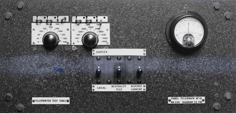
33. Teleprinter Test Panel
A Panel, Telegraph No. 18 - diagram TG.744 - is provided to enable
Teleprinters No. 3A to be tested and adjusted in the Instrument Room. The
panel may be mounted on a table provided locally, or at a bench position.
Mounted on the panel are a Milliammeter No. 17, a Rheostat "R" and a
Rheostat "S" - connected in series - and three switching-keys, labelled to
indicate their functions. The panel is connected to two Jacks No. 49 on the
Panel, Telegraph, No. 33, mounted above the Concentrator jack field. The
power required for testing is 24 volts ±, and is supplied from Panel,
Telegraph No. 9 at the Test Bay, via the line side jack. The earth lead for
the Panel is obtained from the Test Bay, also via the line side jack. Three
Jacks No. 44 - labelled respectively "A" TROLLEY JACK, "B" TEST JACK and "C"
LINE JACK - should be fitted, together with two Sockets and Switches for
Plug, Wall No. 8 and one Box, Service, E.L. No. 0, on the table or bench
which accommodates the Teleprinter Test Panel. A typical layout for this
equipment is shown n Diagram TG.744. The method of carrying out various
tests as required on the Teleprinter Test Panel is detailed in D5003.
34. Intermediate Distribution Frame
A standard I.D.F. Diagram EC.1533, TG.833 is provided. It consists of 2 or 3
verticals, each/vertical can accommodate 8 Strips, Connexion No. 41A fitted
on the front and on the back. This number will provide sufficient tags for
the largest Offices; the strips should be requisitioned separately according
to local requirements. The allocation of connexions to the verticals is
detailed in P3002.
35. External Wiring of Panel Equipment
This work is carried out locally as specified in D3001.
36. Wiring of Instrument Table Position
The apparatus associated with the SEND and RECEIVE circuits is mounted on
the trap covers, on the Instrument Table for Teleprinters No. 3A. Full
details of this apparatus and its wiring are shown on Diagrams Misc. 4296
and TG.827.
POST OFFICE
ENGINEERING DEPARTMENT
TECHNICAL INSTRUCTIONS
TELEGRAPHS
GENERAL
D3001
Issue 1, September 1934
PANEL-MOUNTED TELEGRAPH APPARATUS
FOR PUBLIC CIRCUITS
Installation of Equipment
1. Scope of Instruction
This Instruction details the work to be performed by the engineering staff
in connexion with the installation of the panel-mounted equipment employed
for public telegraph circuits. A general description of this equipment is
given in D1001.
2. Erection of equipment
The position allotted to the panel-mounted equipment in the Instrument Room
is determined by the Telegraph and Telephone Department (Traffic Section),
who furnish plans to the Engineer-in-Chief. H.M. Office of Works should be
consulted by the Superintending Engineer of the District concerned, to
ascertain whether, having regard to the total weight of the equipment,
structural alterations or floor strengthening will be required. In this
connexion, it should be noted that the total weight of one suite of bays,
i.e., two Apparatus Bays and one Test Bay, is approximately 8cwt. (or 1cwt.
2qrs. per foot run). Wherever possible, a concrete base should be provided,
to which the frames will be secured by means of Lewis bolts. A typical
example of the method of erection and fitting of frames is shown in Diagram
EC1532.
3. The type of panels required for individual issues of
"Equipments, Telegraph," and their position on the frames is decided by the
Telegraph and Telephone Department, who furnish a plan for the. layout of
the panels and the disposition of the equipment for individual circuits. In
allocating panel positions, consideration is given:-
-
To the requirements of spare and reserve positions,
in order to distribute them over the whole equipment and thus to
equalize the load of the working circuits on each Test Bay.
-
To avoid having all the circuits serving two centres
on one particular suite.
-
To arrange for the equipment associated with circuits
requiring close attention to be placed in the most favourable position,
i.e., at a convenient height. For this reason panel No. 2 will be given
the "set 2" position, as shown in Diagram EC1551,
4. Equipment to be requisitioned
When an estimate for an installation has been authorized, one or more suites
of bays should be requisitioned as required. The items required for one
suite are as detailed below:-
1 x Equipment, Telegraph, D 9778 (Test Bay, fully
equipped and wired).
2 x Equipment, Telegraph, D 9777 (Apparatus Bays - fully equipped and wired
- each with 4 Panels, Telegraph, No. 1-5 as specified).
The following additional items will be required for one
suite; these should be requisitioned separately:-
Relays, Standard, BN or GN - as required.
1 x Cap, Lamp, No. 2.
50 x Fuses No. 1/1.
1 x Guard Rail for panels.
45 x Lamps, Glow, 100V., E.S., 16 c.p. or 32 c.p., as required.
1 x Lamp No. 2, 4-volt.
1 x Lamp No. 2, 40-volt.
1 x Voltmeter No. 27 (portable voltmeter, for balancing duplex circuits).
6 x Pegs No. 16, Green.
10 x Plugs, No. 121, fitted with Cord, Instrument, No. 104
1 x Coil, Induction, No. 14 and 1 x Condenser, M.C., No. 102 are required
for a telephone circuit. To be fitted locally in place of the centre
Resistance Lamp on "Equipments, Telegraph D 9778".
6 x Bolts, 3/8in. B.S.W. x 1 in. Hexagonal Head, Mild Steel, Blued or
Lacquered (for bolting individual bays together).
12 x Lewis bolts (as required - for fixing one suite to the floor).
5. Panels
Individual panels will be provided for particular circuit requirements as
specified by the Telegraph and Telephone Department (Traffic Section). The
various types of panel, and the type of circuit for which they are
appropriate, are detailed below. Any one of these panels can be obtained on
requisition, if at any time it is required to change the type of circuit to
be accommodated on existing equipment.
Panel, Dummy, No. 1 - (For vacant positions on Apparatus Bays, if required).
Panel, Telegraph, No. 1 - Diagrams TG 734, TG 767 (for 2-way
simplex teleprinter circuit)
Panel, Telegraph, No. 2 - Diagrams TG 735, TG 768 (for loop or single-wire
duplex teleprinter circuit, using a vibrating type relay).
Panel, Telegraph, No. 3 - Diagrams TG 736, TG 768 (for loop or single-wire
duplex teleprinter circuit, using a Relay, Standard, BN).
Panel, Telegraph, No. 4 - Diagrams TG 745, TG 769 (for loop or single-wire
duplex or Special Event simplex teleprinter circuit).
Panel, Telegraph, No. 5 - Diagrams TG 747, TG 770 (for 2-line simplex
teleprinter circuit - C, B system).
Panel, Telegraph, No. 6 - Used in conjunction on the Test Bay, see Diagram
TG 741.
Panel, Telegraph, No. 7 - Used in conjunction on the Test Bay, see Diagram
TG 741.
Panel, Telegraph, No. 8 - Used in conjunction on the Test Bay, see Diagram
TG 741.
Panel, Telegraph, No. 9 - Diagram TG 743 (Fuse and. Distribution panel for
Universal Line batteries).
Panel, Telegraph, No. 10 - Diagram TG 742 (Fuse and Distribution panel for
Loop batteries and for Local Line batteries).
Panel, Telegraph, No. 11 - (Lamp panel for 12 Battery Resistance lamps).
Panel, Telegraph, No. 12 - Diagram TG 737 (Lamp panel for three Battery
Resistance lamps).
Panel, Telegraph, No. 18 - Diagram TG 744 (Test panel for Teleprinters No.
3A).
Panel, Telegraph, No. 21 - Diagrams TG 801, 750. (Test panel for Telegraph
Relays - see P.W.s & Telex, C1136).
Panel, Telegraph, No. 23 - Diagram EC 1551 (Fuse and Distribution panel).
Panel, Telegraph, No. 24 - Diagram EC 1551 (Alarm panel for use with "Panel,
Telegraph, No. 23").
Panel, Telegraph, No. 33 - (Cord Test for Concentrator Plugs and Cords).
Panel, Telegraph, No. 34 - Diagram TG 865 (Synchroscope for testing speed of Teleprinters
No. 3A; where authorized by Headquarters).
Panel, Telegraph, No. 38 - (Monitor and Test panel for L.P.S. circuits
accommodated on No. 39.
Panel, Telegraph, No. 39 - (Accommodates 2 L.P.S. circuits).
Click here for a typical
example of one suite comprising of 2 apparatus bays and 1 test bay - Drawing
TG746
PANELS, TELEGRAPH
A detailed description of each of these panels is given in
the series of Engineering Instructions, Telegraphs, General D1010 to D1129.
D1011 - Panel, Telegraph No. 1.
D1012 - Panel, Telegraph No. 2.
D1013 - Panel, Telegraph No. 3.
D1014 - Panel, Telegraph No. 4.
D1015 - Panel, Telegraph No. 5.
D1016 - Panel, Telegraph No. 6.
D1017 - Panel, Telegraph No. 7.
D1018 - Panel, Telegraph No. 8.
D1019 - Panel, Telegraph No. 9.
D1020 - Panel, Telegraph No. 10.
D1021 - Panel, Telegraph No. 11.
D1023 - Panel, Telegraph No. 18.
D1026 - Panel, Telegraph No. 33.
D1029 - Panel, Telegraph No. 39.
PANELS, TELEGRAPH
PICTURES
Panel, Telegraph No. 18

Panel, Telegraph No. 18A

Panel, Telegraph No. 21

Panel, Telegraph No. 34
|