MANUAL SWITCHING OF TELEPRINTER CIRCUITS | |||||||||||||||||||||||||||||||||
|
An extract from the The Introduction of Manual Switching
Circuits in the Public Telegraph Service The first part of this article outline the reason for the Introduction of a teleprinter intercommunication system for the Public Telegraph Service, with switching on a manual basis, and describes the switching network provided, and the programme of conversion involved. The second part will deal with the physical and circuit features of the equipment employed. Introduction Firstly, it is necessary to stress that but for the war,
manual switching would never have been applied to the network, since the
system of automatic switching, which had been designed and subjected to
satisfactory large-scale field trials prior to the outbreak of hostilities,
would have been operative. This automatisation scheme was, however,
suspended at the outbreak of war and thus, during the early war years, the
telegraph traffic continued to be handled over the existing network of
point-to-point circuits, augmented as far as possible to meet the steadily
increasing traffic, the trend of which is shown in Fig. 1.
FIG. 1 - PUBLIC TELEGRAPH TRAFFIC With this method of working, a high proportion of the total traffic was dealt with at the Zone Centres but the loss of the telegraph instrument rooms at the C.T.O., Liverpool, Bristol and Birmingham during the 1940/41 blitz, rendered it necessary as a matter of urgency to de-concentrate the telegraph traffic away from the large and vulnerable towns. Under the de-concentration scheme many additional Area Centres were set up, and arranged in "triangles" of three, each triangle having at one or other of the area centres concerned teleprinter point-to-point connections to all other "triangles." The scheme was brought into effect during the summer and autumn of 1941, and although successful in relieving the zone centres of a considerable volume of traffic it resulted in a substantial increase in the number of retransmissions per telegram, with consequent increase both in staff hours and transit time. The immediate problem of security being resolved, attention was next directed to a means for restoring the quality of service without a corresponding increase in man-power requirements. A reduction in the number of retransmissions by the introduction of switching methods was adjudged to provide the most promising solution, the basis of the switching scheme proposed being the connection of all outlets from a particular "triangle" to all other "triangles" via a switchboard, thus eliminating the need for retransmissions at the intermediate area centre to which these outlets were connected. At the outset, therefore, the switching scheme was designed primarily as a means of teleprinter communication between area centres only, and some thought was given to the location of the necessary switchboards at appropriate area centres. Study of the equipment requirements showed, however, that more efficient utilisation could be achieved by installing the switching centres at certain selected zone centres, such that, provided the switching equipment was sited in accommodation not more vulnerable than the V.F. equipment, adequate safeguards against dislocation of the service by air attack could be obtained. The decision was taken, therefore, to site the switchboards at selected zone centres of which there were ultimately to be six, and for the purpose of a field trial to install suites of five positions in protected accommodation in the basements of the H.P.O.s at Birmingham and Leeds. The urgency of the scheme necessitated the avoidance of
and delay which the design and provision of special switchboards would have
involved, consequently the type of switchboard used by the armed forces on
the Defence Teleprinter Network (D.T.N.)
was adopted for the field trials with only such modifications as were
necessary to meet the differing technical requirements of the Public
Service. Although by this means the utmost expedition was achieved in
providing and installing the field trial and subsequent equipment, the P.O.
Factories Department, which undertook the manufacture of the equipment, was
already fully engaged in the supply of D.T.N. switchboard equipment to meet
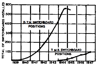
the ever-growing demands of the fighting services, and the authors desire to
place on record their wholehearted appreciation of the good services
provided both by the staff and works personnel of the Factories Department,
under difficult conditions, in meeting these joint requirements, the measure
of which is given by the curves in Fig. 2.
FIG. 2 - D.T.N. AND T.M.S. SWITCHBOARD PROVISION The five-position suites at Birmingham and Leeds, comprising the field trial equipment, were brought into service on January 14th, 1944, and from the outset provided a satisfactory service, and afforded a material reduction in retransmissions. Further improvements in the service were expected as more offices were connected, and hence the extension of the switching system to the telegraph network as a whole, by appropriate stages, each of which would contribute its quota to the improvement of the national service, was approved. It should perhaps be recorded for those readers not familiar with teleprinter switching systems that the circuits terminated at these switchboards are suitable only for the transmission of telegraph traffic and that demands are passed to switchboards by teleprinter messages. ROUTING OF TELEGRAPH TRAFFIC The number of telegraph offices at which telegrams may be
handed in is approximately 14,000, varying in size from small Post Offices
to the C.T.O. in London. It follows that it was and is quite impracticable
to provide direct circuits between all telegraph offices, or even all large
offices, hence for telegraphic communication purposes the country was
divided into 11 zones, each of which was divided into areas, and sub-divided
into groups. Small telegraph offices known as minor offices were connected
to their group centre, which acted as the transmitting office for all such
minor office traffic. Similarly, the area centre acted as a transmitting
office for all group centres in its area, and the zone centre for its area
centres. Direct telegraph circuits were provided interconnecting all zone
centres (excepting Belfast, which had connection to only seven zone
centres), and in addition, where traffic justified their provision, between
zone centres and area centres in other zones, or between area centres. Fig.
3 (a) shows an arrangement of zones and areas illustrating the foregoing
principles, and also the trend in the immediate pre-war years to concentrate
more traffic on the zone centres, by reduction of the number of area centres
and connecting group centres to zone centres direct. The technical
arrangements adopted to provide the teleprinter point-to-point circuits
concerned have been the subject of previous articles and will not be
described here.
FIG. 3 - TYPICAL ROUTING OF POINT-TO-POINT TELEPRINTER CIRCUITS The foregoing covers the purely telegraphic network, but the description would not be complete without reference to the phonogram service and telephone-telegraph system, which together contribute some 40 per cent. of the traffic to be handled by the Inland Service. Telegrams handed in by telephone nay be received either from telephone subscribers or from call offices or kiosks, this service being known as phonograms, or from small Post Offices from which the telegram traffic does not justify the provision of teleprinters, this service being known as telephone-telegrams. The centre at which this telephone traffic is received, and at which special phonogram and T.T. positions are provided and staffed, is known as the "appointed office," and has at least group centre status. Thus onward transmission from the appointed office is nearly always by teleprinter. The net effect of the point-to-point system of working above described was that a large volume of traffic was concentrated at the zone centre, and although this resulted in efficient utilisation of the main links, an obvious drawback was that a large proportion of the traffic was subject to one or more retransmissions before reaching the objective office. As telegrams have to be circulated for distribution at each transmitting point, and then lined up for onward transmission over the next link, an appreciable aggregate delay was thereby incurred, and additional staff and apparatus costs were clearly involved. De-concentration Arrangements Manual Switching-Initial Routing Arrangements With these arrangements, not more than two switchboards were involved in setting up any connection, and the traffic from area centres requiring two switching operations, particularly in the early stages of the scheme with only two or three switchboards opened, and few group centres connected, would be small. In the ultimate, however, with all switching centres opened, a fair proportion of area centre traffic and a large proportion of group centre traffic would require two switching's, although no real difficulty was expected, as most of the traffic over the D.T.N. network was being similarly routed without difficulty. Experience during the earlier stages of the scheme showed, however, that the operator output on calls routed through two switchboards was considerably lower than on calls through only one switchboard, the normal tendency towards which was increased somewhat by the effect of the occasional connection of follow-on calls to inter-switchboard circuits which had not been cleared at the distant end, resulting in delays in answering at the second switchboard, as well as misrouted calls. This difficulty was ameliorated by modifying the inter-switchboard circuits to unidirectional working, but to provide a positive solution the design and provision of inter-switchboard line equipment to give full automatic signalling facilities was put in hand. It was also observed, in connection with the use of bothway teleprinter extension circuits from the switchboards, that operators dealing with outgoing calls resented the connection of incoming calls, and therefore tended to hold connections irregularly until ready to originate the next call. These factors, taken in conjunction with a proposal to
extend the number of group centres to be connected to the switching network,
led to the design of modified routing arrangements employing unidirectional
circuits.
FIG. 4 - TYPICAL SWITCHING ARRANGEMENTS, USING UNIDIRECTIONAL CIRCUITS Manual Switching-Modified Routing Arrangements The routing of switched public traffic via two switchboards has thus been eliminated, but a small number of unidirectional inter-switchboard circuits have been retained in use, for the routing of service traffic. Later, the use of double switched connections /or a limited amount of public traffic, to meet special cases where on balance a service advantage is realised, is a possibility, and has not been precluded by the technical arrangements made. The use of a small number of bothway teleprinter extension circuits for special purposes will of course continue, mainly for the provision of service and maintenance facilities, as follows:-
Transmission Limits Teleprinter extension circuits (switchboard to area or group centre teleprinter) are either a combination of physical line and V.F. channels, or are wholly physical. In the former case, the physical section must not exceed the limiting distance for negligible distortion, given in Column 4 of Table 1, whereas in the latter case the limits in Column 3 of Table 1 are applicable, and as the distortion may not then be negligible, not more than 2 V.F. channels in tandem may be employed on connections including such circuits. The limits quoted in Table 1 have been determined with specific regard to the method of working employed on the T.M.S. network, i.e. 2-wire simplex, using double-current signalling. TABLE l
Note 1.-The limits quoted for Twin or Multiple Twin cables apply to side and phantom circuits. Circuit Provision To meet conditions where congestion may exceptionally arise on individual routes outgoing from switchboards, the operating instructions ensure that if the second attempt to secure connection by a forwarding office is ineffective, then the call will be routed on an overflow basis to a teleprinter position at the switching centre concerned for subsequent retransmission. Experience has shown that the amount of overflow traffic, with the above circuit provision, is very small. CONVERSION PROGRAMME The initial programme provided for 15 separate stages to obtain completion of the network, the necessity for the provision and opening to service of the six switching centres arising as follows:-
In addition to the requirements for the manual switchboard installations, the conversion programme also called for the installation of extension teleprinter positions at the various centres connected to the switchboards, and for the necessary provision and rearrangement of V.P. systems to meet the revised line network. To deal in any detail with this latter aspect would perhaps be outside the scope of this article, nevertheless it will be clear that careful planning and close control were necessary to ensure the fulfilment of programme dates while, at the same time. maintaining continuity of service. A brief review of the progress made with the conversion
programme and the results obtained follows. It will be noted that in the
event a number of stages have been merged to accelerate the programme, and
two stages (5 and 9) deferred for later introduction. Stage 1 of the conversion was based on the provision of full switching facilities to the Derby-LeicesterNottingham triangle of area centres, with switchboard installations (using Switchboards, Teleprinter No. 17) at Birmingham and Leeds. Peterborough, for security reasons, and exceptionally the large group centres of Rugby and Coventry, were also connected as fully switched offices. The remaining group centres in the triangle continued to work to their home area centres over point-to-point teleprinter circuits, as illustrated in the inset to Fig. 5. From this figure, the line network for Stage 1, comprising 200 working circuits, may be discriminated. The outlets from the switching network providing access to the unconverted portion of the existing network are also shown in tabular form in Fig. 5. The extension teleprinter circuits installed at these "partially switched" centres were, of course, of the same design as those provided at the fully switched offices, as described later. After a period of operation with dummy traffic for the
purpose of staff training, the trial network was opened for live traffic on
January 14th, 1944. Special traffic returns were taken during the first few
months of working, and showed that the average transit time per telegram
from the full switching offices had been improved by approximately 20 per
cent., and the number of RQs (service messages regarding apparent errors in
received telegrams) had been reduced by nearly 50 per cent. The number of
retransmissions saved was estimated at 0·8 per telegram. Still further
improvements in service were confidently expected as more offices were
connected to the network.
FIG. 5 - LINE NETWORK FOR INITIAL STAGES Stage 2 Arrangements By reason of the different operating procedure employed on the T.M.S network, compared with the D.T.N., it was found during the initial trial that a slight risk was incurred of duplicate connections being established (1 in 1,172 messages), an occurrence which can cause material service difficulties. To preclude such occurrences, a new cord and position circuit design was evolved, and given a field trial on an experimental suite of four positions at Manchester, which comprised the switchboard requirements at this centre for Stage 2. Opportunity was also taken to include a number of refinements in circuit design which bad been developed meantime, as well as of physical details, the resulting switchboard being known as the Switchboard, Teleprinter, No. 17A. The Stage 2 network was opened for service on December
31st, 1944, with satisfactory results; the automatic "engaged-test" facility
incorporated in the Manchester switchboard was proved to be completely
effective in preventing duplicate Arrangements for Stages 3 and 4 Extension of the equipment at the three existing switching centres was necessary, the number of positions being increased to 13, 14 and 9 at Birmingham, Leeds and Manchester respectively, and opportunity was taken to install the extended suite at Birmingham in above-ground accommodation, and thus to improve the staff working conditions. At the completion of this phase some 28 per cent. of the total public telegraph traffic was being handled by switching means, with a substantially improved grade of service. Nevertheless, traffic observations showed that further improvements could be realised by the introduction of unidirectional working, as previously described. Arrangements for Stages 6, 7 and 8 The installation work involved the provision of a suite of 20 positions at Leeds, replacing the existing suite of 14 positions in refuge accommodation; of 21 positions at Birmingham, to replace the existing suite of 13 Switchboards, Teleprinter No. 17; of 12 positions at Bristol, and an extension of the Manchester suite by 9 positions (Fig. 6). Also all regions were involved in the provision of additional extension teleprinter positions, as well as the rerouting of V.F. systems to meet the revised line arrangements, illustrated by Fig. 4, and provision of new systems to cater for new offices connected to the network. An incidental product of the revised method of working
was that certain rearrangements of the switchboard face layout to give
improved operating facilities were made possible, and were implemented as
part of the installation work for this phase, viz. the division of the
combined answering and calling jack-field, with 3-panel multiple repetition,
into separate incoming and outgoing multiples, with 12-and 4-panel multiple
repetition respectively. As a result, the jack-field was simplified from an
operating viewpoint, and a material reduction was obtained in the overall
height of the multiple field. The self-evident benefit gained by this
reduction in height was supplemented, to some extent, by a saving in
ineffective time as a result of the reduction in the number of appearances
of the calling lamps, and consequent reduction in the number of cases of
simultaneous answering by two or more operators.
FIG. 6 - TELEPRINTER SWITCHBOARDS AT MANCHESTER With the introduction of this phase, the provision of equipment at the Birmingham, Leeds and Manchester switching centres catered. for the ultimate requirements, and from a traffic viewpoint, al 24 area centres and a number of group centres in the zones covered by these switching centres had been provided with full switching facilities. The modified and enlarged network was opened for service on June 23rd, 1946, and functioned satisfactorily from the outset both as regards engineering and traffic facilities. Stage 10 The proportion of the total public telegraph traffic being passed over the switching network at this stage was approximately 40 per cent., or some 70,000 telegrams daily. Completion Stages The number of switchboard positions installed in the C.T.O., London, to meet the phase I requirements, was 16. For the ultimate requirements 39 positions will be required, with a multiple capacity for 240 incoming circuits and 560 outgoing circuits. The estimated number of switching circuits in use at the
completion of the conversion programme is 1,547, with a total of 134
switchboard positions. The proportion of the public telegraph traffic
passing over the switching network is estimated to reach 75 per cent. of the
total.
An extract from the The Introduction of Manual Switching
Circuits in the Public Telegraph Service The previous part of this article stated the reasons for the introduction of manual switching in the Public Telegraph Service and described the switching network and the programme of conversion. This part describes the switchboards and associated apparatus employed.
Signalling Principles
FIG. 1 - SKELETON DIAGRAM OF THROUGH CONNECTION Following the precedent set by the D.T.N. the line signalling arrangements constitute what may be termed a pulse signalling system. This system is based upon the maintenance of marking (-80V battery) conditions, corresponding to the "rest" condition of the teleprinter, on the line at all times except when engaged in calling, teleprinting, or clearing, each of which operations is effected by transmitting one or more spacing signals. The signalling conditions in each condition are:-
The Teleprinter Extension Circuit The
answer-back signal is used, primarily, to verify connection to the correct
office at the beginning and end of each message and permits messages being
received on unattended teleprinters. It is also used in conjunction with the
paper failure alarm as a warning to the sending operator that a paper fault
has occurred, the circuit being arranged so that answerback signals are
transmitted by the faulty teleprinter so long as the paper fault persists. A
calling lamp is provided on each position and is arranged to remain alight
after an incoming call until it is reset by a key. A key is also provided to
facilitate attention to paper faults and the clearing signal is transmitted
by a separate key as already mentioned. The circuit arrangement of an
extension office teleprinter is shown in Fig. 2.
FIG. 2 - EXTENSION OFFICE TELEPRINTER CIRCUIT On connection of an incoming call the WRU contacts close due to the caller sending the "Who are you?" signal and the answer-back electromagnet AB1 operates to the charging surge in condenser QA. During the consequent transmission of the answerback signal, contacts AB1 close and operate the calling relay L which holds to a contact of the reset key. The calling lamp glows until reset by the operator attending to the message. On outgoing calls, the operator calls the switchboard, using the teleprinter keyboard as already described, and the local calling lamp circuit is not operated. The call is terminated by sending a long spacing signal by the clearing key. When a message is being received, the paper alarm contacts PF close during each character for approximately 60 milliseconds. Relay P, which is made slow-to-operate by condenser QB, does not respond to these impulses from the PF contacts. In the event of a paper fault, however, the contacts close for at least 150 milliseconds so that relay P operates, causing a relief relay PF and the answer-back electromagnet also to operate. Relay PF locks in the operated position and applies earth to start a flicker pulse generator while also connecting the calling lamp to the flicker pulse. The lamp flashes until attention is given and an audible alarm in the instrument room is operated from the pulse generator. The answer-back mechanism operates so long as the PF contacts on the teleprinter remain closed and, with a transient fault, the sending operator may proceed with the message when the answer-back signals cease. With a persistent fault, the operator attending to the faulty machine can cut off the alarm conditions by operating the "Paper Alarm Cut-off" key and, the answer-back mechanism having stopped, can advise the caller of the action to be taken. Normally, calls are held and the fault cleared, to minimise risk of duplication of messages.
SWITCHBOARD LINE EQUIPMENT
Incoming and Outgoing Teleprinter Extension Circuit. A universal form of line equipment, the circuit of which is shown in Fig. 3, is used for these circuits. The relay apparatus is mounted on a 6 ft. 6 in. rack, 1 ft. 8.5in. wide, which caters for 60 lines; a typical line rack is shown in the background of Fig. 4. Each rack is provided with fuse mountings for the 6V power supplies to the calling and F.L.S. lamps, and for the 6V supplies to the relays. Connection strips are provided behind the rack for the F.L.S. strapping for groups of outgoing circuits and for common service cabling. The cabling from the I.D.F. terminates directly upon the relay panels. Separate multiples are provided on the switchboard for incoming and outgoing circuits, the jumpering on the I.D.F. to the line equipment being varied, as indicated in Fig. 3. The calling relay L, which is effective only on incoming circuits, is polarised by a metal rectifier so that it responds only to spacing (+80V) signals. It provides a loop across the line wires so that the caller receives his own calling signal until a plug is inserted at the switchboard, when the loop is disconnected by the E relay. Bothway Extension Circuits
FIG. 3 - EXTENSION LINE CIRCUIT, I/C AND O/G, SHOWING CONNECTION OF PLUGGING-UP AND THROUGH CONNECTION JACK The principal
addition to the circuit of Fig. 3, apart from the fact that both calling and
F.L.S. lamp circuits are jumpered on the I.D.F., is a slow-releasing relief
relay for relay L which steps forward the F.L.S. signal on receipt of a
calling signal, the release lag of the relief relay being sufficient to mask
any intermittent operation of relay L which may occur during normal calling.
FIG. 4 - SWITCHBOARD, TELEPRINTER No. 17B - RACK MOUNTED EQUIPMENT One bothway circuit occupies the rack space for two unidirectional circuits.
Inter-Switchboard Circuits Although the design of the system provides for through clearing and the supervisory lamps at both switchboards commence to glow virtually simultaneously, it cannot be ensured that both operators will clear down the connection at the same time. It is necessary, therefore, to provide extended engaged facilities so that the F.L.S. at the outgoing end does not indicate a free circuit until the plug has also been withdrawn at the incoming end. At the outgoing end of the circuit relay G is operated and locks via its own contact when the operator inserts a plug on setting up the call. At the same time, the slow releasing relay F is operated and remains under control of the sleeve relay E. If, when the call is cleared, the incoming operator breaks the connection first, a loop is applied to the S and R lines at the incoming end via the calling relay L. When the outgoing operator then withdraws the plug relay E releases and applies + 80V to the S line via contact F1. The positive signal so transmitted passes round the loop at the incoming end and returns to the line winding of relay G which is connected so that the flux produced neutralises that due to the holding winding and causes the relay to release. The release of relay F restores the normal -80v condition to the line and prevents the calling relay at the incoming end from remaining operated. If the outgoing operator is the first to clear the connection, the testing signal pulse generated by the combined action of relays E and F cannot return since no loop exists at the incoming end of the circuit. Provision is made at the incoming end, by relays H and J, for a pulse to be sent back to the outgoing equipment when the plug is withdrawn from the jack. Relay G is then released and the F.L.S. marks the circuit as free. A delayed alarm operates after three minutes if, for any reason, an outgoing equipment is not fully released in this period. Such conditions, apart from abnormal operating delays, are indicative of line faults and require investigation. The relay equipment is mounted on racks similar to those used for extension line relays (Fig. 4), each rack accommodating 24 incoming and 24 outgoing circuits. The alarm lamps for outgoing circuits are mounted centrally on the relay panels.
SWITCHBOARD POSITIONS The overall dimensions of each position are 2 ft. 5 in. wide, 3 ft. 3 in. deep and 6 ft. 6 in. high. In addition to the items of equipment visible in Fig. 6, and subsequently described, the switchboards contain a framework at the rear on which are mounted the 75 cord circuit relays and 9 position relays, together with associated rectifiers, condensers and resistors. Chain supported multiple cable bearers are provided at the rear of the jack field, together with a cable rack for supporting miscellaneous cables, and a connection strip to facilitate their termination. Signalling earth, lamp return and rack earth bus-bars are also provided on each position. Multiple
and Face Equipment
F1G. 6 - FRONT VIEW OF SWITCHBOARD, TELEPRINTER No. 17A, WITH DUMMY END POSITION AND C.T.S. The white opal lamp mounted over the centre style bar on each position provides a visual "night alarm" indication of an incoming call, or clearing signal on an established connection. The two red opal lamps mounted centrally beneath each jack panel, and designated "engaged" lamps, provide a visual alarm that the operator has over-plugged an already engaged line, and should take down the connection. Keyshelf Position Teleprinter The teleprinter tape is illuminated by a special lighting fitment mounted on the teleprinter and beneath the teleprinter cover, thus focusing the light on the printing and eliminating any glare to the operator. Cord and Position Circuits Relays SA and SC perform this function for the answering and calling cords respectively and test for a 2500-ohm battery on the sleeve conductor of a free line. If this condition is met, the sleeve relay operates in series with the E relay of the line circuit and applies earth to the sleeve conductor via its low resistance holding winding. The sleeve potential is thus lowered so that no other cord could switch to the engaged line should a plug be inserted elsewhere in the multiple. Any attempt to over-plug is therefore ineffective and harmless. While the SA and SC
relays afford adequate protection, in this way, against the over-plugging of
established connections, it is possible for two such relays to operate and
hold in parallel if the plugs were inserted into the multiple jacks
simultaneously. This cannot readily be avoided in the design of the sleeve
relays themselves and, to prevent such a condition from being maintained,
common relays are provided in the position circuit which apply a
differential current to the high resistance windings of the sleeve relays
for a short interval after a plug has been inserted. This current is
insufficient to de-flux a sleeve relay which has switched to a free line but
ensures the release of any sleeve relay which has operated in parallel with
another. In Fig. 7 it will be seen that the sleeve relays derive their
operating earth via relay P in the position circuit. Relay P is sufficiently
sensitive to operate whenever a plug is inserted, whether the line be free
or engaged, and it releases when the sleeve relay operates. Relay P controls
relays PR and PZ which, on release of P, apply battery, during the release
lag of relay PZ, to the high resistance coils of all operated sleeve relays.
Sleeve relays which are released in this manner immediately attempt to
re-operate and, owing to the inherent differences in the relay timings of
the two cord and position circuits involved, one of them gains sufficient
lead after one or two testing cycles to prevent the second sleeve relay from
operating.
FIG. 7 - CORD AND POSITION CIRCUITS-SWITCHBOARD, TELEPRINTER No. l7A The unsuccessful connection is indicated to the switchboard operator by an alarm. Relay P remains operated until the plug is withdrawn, since in this case the sleeve relay has not operated and disconnected relay P. Relay DD then operates with a delay of approximately one second, due to the effect of condenser QA. Relay DD causes the operator's teleprinter control relay R to apply spacing conditions to the teleprinter receiver which ''races" and feeds out tape. An alarm lamp is also illuminated beneath each jack panel on the face- of the switchboard. This combination of alarm conditions cannot readily be overlooked by an operator and is maintained until the ineffective plug is withdrawn, thus allowing the position relays to restore to normal. The delay imposed by relay DD is necessary to prevent a premature alarm being given during normal functioning of the sleeve relays. When the "Print" (KP) or "Monitor" (KM) key of a cord circuit is operated, relay SK operates and extends the tip and ring conductors of both cords via the position circuit. The SK relays arc arranged, in the well-known manner, so that one only can be operated at a time, other cord circuit keys being rendered temporarily ineffective. Relay H in the position circuit operates in series with the SK relays and removes a holding current from the operator's teleprinter control relay R, leaving this relay free to respond to the conditions applied via the cord circuit tip conductors. The position "Ans./Call" key (KC) is connected normally in the "Answer" condition so that relay R responds to conditions on the tip conductor of the answering cord. In this position the key also provides for operation of relay A in the position circuit if a cord circuit key is operated to "Print." Relay A in operating applies a loop to the tip and ring conductors of the calling cord so that an extension operator who might be connected would receive her own signals as an indication that the through connection had been interrupted. The tip and ring conductors of the answering cord are connected to the switchboard teleprinter receiving relay and transmitter respectively so that the operator is in teleprinting communication with the party connected via the answering cord. If the position
key KC is operated to the "Call" position relay A in the position circuit
releases and relay C operates. The conditions on the cord circuit are
thereby reversed, the switchboard operator being in communication via the
calling cord and a loop being applied on the answering cord. A clearing supervisory
relay (relays CA and CC) is connected in leak with the tip conductor of each
cord, the leak impedance being sufficiently high to have no appreciable
effect upon the normal transmission of teleprinter signals. The line coil of
each clearing relay is connected in series with a condenser and a metal
rectifier. The rectifier is shunted by a resistor so that its effective
resistance in the backward or non-conducting direction is controlled within
comparatively close limits. When the cord circuit is idle and, apart from
short signalling impulses during teleprinting, when it is in use on a
connection a negative potential exists on the tip and ring conductors. The
clearing Circuit condensers are normally charged, via the forward resistance
of the metal rectifiers, to this negative potential. When, during
teleprinting, the negative potential on the line conductors is replaced by a
corresponding positive one the charge on the condenser tends to become
reversed but can only do so via the backward resistance of the metal
rectifier and its shunt. The time constant of the circuit is such that the
energy which can be stored in the condenser in this way during normal
signalling can never reach a value sufficient to operate the relay. The
clearing signal of five seconds' duration, however, ensures that the charge
on the condenser becomes reversed to the full applied positive potential
and, on restoration of the normal negative potential when the clearing key
KCL is released, the charge again reverses and produces a rapid surge of
current in the relay, via the low forward resistance of the metal rectifier.
The clearing relay operates to this surge and holds via its own contact
under control of the sleeve relay. The supervisory lamp glows and all relays
release when the plugs are withdrawn.
FIG. 8 - PLUGGING-UP AND THROUGH CONNECTION PANELS AND CONTROL BOARDS The potentials available at the cord circuit for operating the clearing relays depend upon the actual voltage of the nominal 80+80 volt supply at the extension offices and upon the total resistance of the sending and receiving lines and instrument terminations. The components of the clearing circuit have been chosen to ensure satisfactory operation on lines up to 1,200 ohms single-wire resistance, using the standard line terminating circuits for teleprinters and V.F. channels and with telegraph supply voltages of 75V or over. At the same time, a safe margin is provided against false operation to teleprinter signals even on lines of zero resistance and with telegraph supply voltages up to 92V. By suitable choice of components a compact design has been achieved in which the size of condenser is reduced to 2µF from the value of 10µF required on previous circuits of this type.
C.T.S., C.S.S. and Dummy Positions The "Night Alarm" key, by which the night alarm
bell is brought into operation, is normally mounted in the panel of the
C.T.S. AUXILIARY APPARATUS
With any of these functions, the lines are disconnected from the switchboard equipment, and the multiple jack positions automatically marked as engaged. A typical installation is shown to the right of Fig. 8, and the circuit connections in Fig. 3, from which it will be seen that all lines are routed through this panel before connection to the switching equipment. The position of the P.U. and T.C. panel in the switch room is largely influenced by the routes available for the main cable runway between the switchboard .and the I.D.F.
Common Equipment Rack The "No Volt" fuse alarm and exchange urgent and non-urgent alarm relays are panel-mounted at the rear of the rack. Speaker
Signalling Arrangements
Cord Circuit Tester
Conclusions Opportunity has been taken to mention the various factors which have influenced the finalised design of the switching equipment now installed at all centres since the experience gained may be of interest and value to others concerned with the manual switching of teleprinter circuits. It should be stressed that without the closest co-operation between the engineering and traffic interests, the experience gained with the initial installations during the war could not have been turned to advantage so speedily as proved to be the case. In this connection, as well as for information contained in this article, the authors wish to acknowledge their indebtedness to Mr. E. W. Cross, of the Telecommunications Department, Inland Telegraph Branch. In conclusion, a development and conversion programme of the nature described could not have been successfully handled without close co-operation between all parties involved, including Headquarters, Regional and Area staffs. Thanks are also due to colleagues in the Telegraph Branch of the Engineerin-Chief's office for assistance given in the preparation of this article.
|
|||||||||||||||||||||||||||||||||
Last revised: August 31, 2023FM2 | |||||||||||||||||||||||||||||||||