CALCULAGRAPH | ||||||||
|
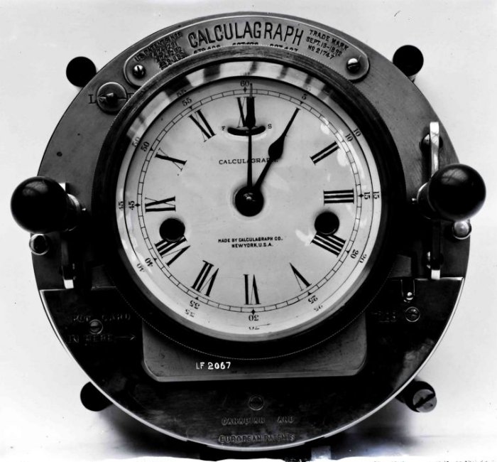
Calculagraph Description of Apparatus Operation By pushing the handle A (Figure 1) backwards the lever B is operated. This movement raises the spindle C and causes the printing mechanism to operate the right-hand dial showing the time of day on the card (Figure 2) . On pulling the same handle forward the lever E is depressed, thus pushing the spindle F upward and causing the mechanism to print the two blank left-hand dials (Figure 2) on the card. On the cessation of the call, the ticket is again inserted face downwards and the handle G is pulled forward. This operates the lever H, which in turn raises the disc J and spindles K and L, and prints the two arrows on the two left hand dials, which indicate the elapsed time between the commencement and termination of the call (Figure 3). The left-hand dial and arrow show the number of minutes up to a maximum of 5. Should the duration of the call exceed this, the centre dial, in conjunction with the left-hand one, will show the entire duration of the call. The right-hand dial shows that the call commenced at 1.45 p.m. and the centre and left-hand dials show that it lasted 3.75 minutes.
Figure 1
Figure 2
Figure 3
Taken from Technical Instructions X1, Clocks and Time Distribution (1927) Pictures
Front view
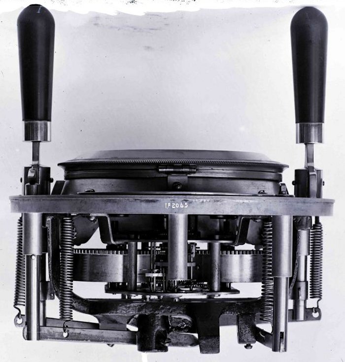
Rear view
Calculagraph in use on a trunk switchboard
|
||||||||
Last revised: July 07, 2023FM2 | ||||||||
 This
instrument is employed for the timing of trunk calls at British Post Office telephone exchanges.
This
instrument is employed for the timing of trunk calls at British Post Office telephone exchanges.