P.O. ENGINEERING DEPT.
ENGINEERING INSTRUCTIONS
MECHANICAL CLOCKS
MISCELLANEOUS
TIME
B 1128MECHANICAL
CLOCKS
Clocks Nos. 51, 53, 55, and 57
1. General
Clocks Nos. 51, 53, 55, and 57 are 8 day timepieces for public offices. They are fitted with a spring-driven chain and fusee movement, similar in most respects to that of Clock No. 3 which is described in B 1122. These clocks are issued with
unpolished light-mahogany cases, which should be stained and polished locally to match office colour schemes.
| No. |
Overall diameter |
Diameter of dial |
Depth (front - back) |
| 51 |
14.75in. |
12in. |
8.25in. |
| 53 |
14.75in. |
12in. |
5.5in. |
| 55 |
12.75in. |
12in. |
8in. |
| 57 |
14.75in. |
12in. |
8.25in. |
2. Clock No. 51
An additional plate and two wheels are fitted to the rear of the mechanism
to operate a second pair of hands. Two 12in.
dials are carried by the clock.
3. To expose the movement, first remove the hands of the auxiliary dial (i.e. the one without the winding keyhole), then extract the holding pins which secure the dial pillars to the movement; unscrew the dial fixing screws and remove the dial. Unscrew the fixing screws from the main dial, and the movement and main dial can then be withdrawn from the case.
4. Mounting
The clock is designed for mounting in a window by means of a horizontal or vertical suspension ironwork (Drawings P/T 104 and P/T 103, respectively), which should be obtained and painted locally. The horizontal suspension is normally employed. The vertical suspension is employed only when the length of span exceeds 7ft., or where local circumstances render the horizontal suspension impracticable. The clock is fitted with an adjustable pallet, for the purpose of correcting small
inaccuracies in mounting. The adjustment instructions are given in B 3101. Any difficulty in
obtaining suspension locally should be referred to the Eng. Dept. (P2), full working dimensions being given.
5. Clock No. 53
This clock has a 12in. dial in an octagonal case and is similar in appearance to Clock No.
51.

Clock No. 53
6. To expose the movement, remove the dial fixing screws and withdraw the dial and movement from the case.
7. Mounting
The clock is provided with a concealed mirror-plate suspension and fixing plates for wall mounting.
8. Clock No. 55
This clock carries two 12in. dials. One face is unglazed.
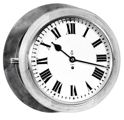
Clock No. 55 with bezel fitted
9. Access to movement
To expose the movement, proceed in accordance with par. 3.
10. Mounting
The clock is designed for mounting in a window frame, by means of a Bezel, Clock No. 1 and is fitted with an adjustable pallet as mentioned in par. 4.

Clock 55 with bezel removed
11. Bezel, Clock No. 1 (Drawing P/T 102) is a circular bronze casting with a 12-in, glazed weatherproof circular opening in the centre.
The bezel is shown fitted in the picture above.
The bezel is designed to be fitted directly into a circular opening in the window frame. Four brackets on the Clock No. 55 are secured to four No. 0 BA
studs which project from the back of the bezel. It is normally stocked with an overall diameter of 17.5in., which may be be reduced to a minimum of 16in. to allow for variation in window design. For installation instructions see B 3004.
12. Clock No. 57
This clock has a circular case but is, in other respects, similar to Clock No. 53.
Clock No. 51 - Drawing - P/T 7 and 63004.
Clock No. 53 - Drawing - P/T 8 and 63006.
Clock No. 55 - Drawing - P/T 9 and 63008.
Clock No. 57 - Drawing - 63017
|